


04.12.2007
There is no need to explain to anyone that the advance of fuel injection for diesel engines is very important. Naturally, for each engine speed, a certain value of the advance angle will be optimal, for example, for idle speed 800 rpm is 3 °, 1000 rpm is 4 °, 1500 rpm is 5 °, etc. ... To achieve such a dependence, which, by the way, is not linear, there is a special mechanism in the injection pump housing. However, this is just a piston (sometimes in the literature it is called a timer), which moves inside the injection pump by fuel pressure and, through a special leash, unfolds a special washer with a wave profile to one or another angle. The piston will be pushed further - the wave of the washer will run onto the plunger a little earlier, it will begin to move and will begin to supply fuel to the nozzle earlier. In other words, the injection advance angle depends on the fuel pressure inside the injection pump housing and on the degree of wear of the washer wave profile. As a rule, there are no problems with fuel pressure. Well, unless the fuel filter gets clogged, the pressure reducing valve plunger gets stuck in the open state, or the blades of the feed pump (inside the high pressure fuel pump) sink in. (FIG. 38, FIG. 39)

fig. Fig. 38 Fig. 39
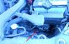
Figure: 38. To fully check the pressure reducing valve, it can be unscrewed from the injection pump. The plunger inside this pressure reducing valve must not be jammed. Whether this is true or not, you can check by pushing the plunger with a match. Under the influence of the hand, the plunger should move easily, compressing the spring.
Figure: 39 ... It is not difficult to unscrew the pressure relief valve on an already removed pump. To do the same without removing the injection pump is already more difficult.
The condition of the pressure relief valve (may be stuck) and the feed pump can be assessed using a manual fuel pump. If the operation of the engine changes after you start pumping with the hand pump while the engine is running, i.e. start to manually raise the pressure in the injection pump housing, then either the valve or the pump is faulty. It is easy to unscrew the pressure reducing valve without removing the injection pump and check. Only on most diesel engines manufactured by "
Mitsubishi »To do this, a corner of the bracket has to be removed with a fine chisel, after which the head of the pressure reducing valve becomes accessible for a special key. By the way, this pressure reducing valve can also be turned out with a long beard (chisel) without using a wrench. (FIG. 40)
Figure: 40. It is possible to raise the pressure in the injection pump housing by pushing the plug (1) of the pressure reducing valve (2) with a thin beard. As a result of these impacts, the spring (3) will push the plunger (4) more strongly and it will close the fuel discharge hole (5). To return the plug back (to reduce the pressure in the high pressure pump housing), it is necessary to punch the plug down harder so that it compresses the spring completely and pushes the plunger so as to push out the stopper (6). After that, both the plunger and the spring fall out easily. Next, you need to turn the pressure reducing valve and punch the plug back with a thin beard. Then put everything in place and try again to adjust the pressure.
There, all the seals are made on rubber rings (torics) and a strong tightening is not required. If this valve is intact, its plunger is not stuck in the open position, then a malfunction of the feed pump should be suspected. Provided that when pumping fuel, the engine becomes smoother. True, if fuel with air bubbles flows from the overflow (return) line when the engine is running, then the first step is to eliminate the air leak. Because if there is air leakage, it is difficult to create the required pressure in the high-pressure fuel pump, even with a well-functioning feed pump. But problems with air suction are a separate topic. Here we just note that air leaks, even with external power supply, i.e. when the fuel canister is above the high-pressure fuel pump, it is possible through the high-pressure fuel pump oil seal and through the non-tightness of the central plug on the cast-iron part of the high-pressure fuel pump. This plug is used to accurately set the injection pump according to the angle of the fuel supply (it is unscrewed, the micrometer head is installed and the stroke of the plunger is measured, this procedure is described in almost all injection pump repair manuals). With a completely serviceable high pressure fuel pump, even if it was previously airborne, after 10 minutes of engine operation, there are no air bubbles in the overflow line.
So, the injection advance angle depends on the engine speed. To save fuel, achieve high power and in terms of ecology, it will be better if this lead angle changes taking into account other engine operating conditions, such as the load on the engine, boost pressure, temperature, etc. But all these conditions can be fully taken into account only for electronically controlled injection pumps. For conventional mechanical units, only the fuel pressure in the injection pump housing and, on more modern units, the engine coolant temperature are taken into account. The piston in the lower part of the high pressure fuel pump moves depending on the fuel pressure and through a special steel "pin" slightly unfolds the profile washer (the same washer is forcibly turned by the leash from the heating device mechanism). As a result, the wave protrusion of the washer will run into the plunger earlier, and it will begin its movement earlier. This entire system was calculated and made at the factory and at the very least did its job. Until intensive wear begins. It became intense because the fuel pump began to receive unlubricated fuel (our "dry" winter fuel, like kerosene, contains almost no heavy fractions, which provide lubrication of all rubbing parts), fuel with air and just dirty fuel ( with abrasive). However, ordinary old age also does its job. As a result, the protrusion on the washer begins to run a little later on the plunger, and that, in turn, begins its movement a little later. In other words, a later injection starts. The beginning of this phenomenon looks like this. The engine is idling and shakes slightly due to different wear of the injectors. We add turns to it. At about 1000 rpm, the engine stops shaking and seems to freeze - it works evenly - evenly. We are also increasing the speed. And suddenly, in the range of 1500 - 2000 rpm, shudders appear. These jerks (shaking) can appear both with a smooth, but intense, and with a slow increase in speed. Blue smoke comes out of the exhaust pipe during the shaking. When the engine is fully warmed up, shaking around 1500-2000 rpm disappears. This is at the very beginning of the defect development. Then the shaking does not disappear even after the engine warms up. Exactly the same shaking appears if you raise the injection pressure at the injectors. In this case, if the high pressure fuel pump is worn out, late fuel injection will also result. We get rid of this phenomenon by turning the injection pump housing to an earlier injection. Sometimes you have to turn the injection pump almost to the stop. But before you do this, listen to the engine running. When a diesel engine has too early injection, it starts to work harder (they also say that its valves knock). And if you make sure that 50-100 rpm before the start of shaking, this hard component in the acoustic background of the diesel engine has disappeared, then you definitely need to turn the injection pump. It should be noted here that worn-out diesels have a piston-to-cylinder clearance that is very large and therefore they begin to work hard even with an absolutely correct injection advance angle. The use of a stroboscope to set the injection advance is not entirely justified in our case. Let's not say that stroboscopes more confidently catch with their microphone the sound of an already heavily worn injector. If the injector is in good condition and the fuel supply pipe is fixed properly, the stroboscope lamp, as a rule, malfunctions. Using a stroboscope, you can set the injection advance at idle. It is this lead that is given in the technical documentation. But the wear in the high pressure fuel pump is uneven. And very often, setting an advance along the mark with the help of a stroboscope at idle speed, we do not get rid of the shaking at the speed caused by late fuel supply. Therefore, we recommend that you be ahead by ear. With the wear and tear that our diesel engines have, this is a more acceptable way. Indeed, this is the only way to compensate for late injection caused by low fuel pressure in the injection pump housing due to wear of the feed pump. This is almost the same as adjusting the ignition timing for gasoline. You can use the instruments to set the ignition timing only at idle speed (and another is not offered by the repair manuals), but due to a malfunction, for example, a centrifugal regulator, the car will not run. It is clear that it needs to be repaired or changed. But you can, by turning the distributor, set an acceptable ignition timing by ear. The only difference is that for gasoline engines, the criterion for correctly setting the ignition timing without using devices will be knocking knocks and engine power, and for diesel engines - shaking, smoke and knocking in the engine.
It has already been mentioned above that most of the problems of the injection pump are due to all kinds of leaks and leaks. For example, the plunger has worn out, a leak has occurred, so it does not create pressure. And if you replace the fuel with a thicker one? Then the increased gaps in the mating parts will seem to become smaller. And the injection pump will work as if it has no wear and tear. It is very easy to thicken the fuel. Add, as mentioned above, any engine oil to it. Of course, I don’t want to drive so much - it’s too expensive fuel (and it’s troublesome to constantly prepare thick fuel). But for checking the condition of the injection pump (as well as for successfully selling a heavily used car in the market), this technique is useful. In the cold season, because of natural laziness, in order to make the fuel thick, we simply cool the injection pump. For example, a car with a diesel engine comes with a complaint that it does not start well if it stands for five minutes, but the engine is still hot. We start this car (indeed, sometimes we have to turn the starter for 30 seconds), warm it up for another 10 minutes and turn it off. After that, we open the hood for it and cool the injection pump with snow. Within the same 5 minutes. If, after this operation, the engine starts up better than the first time, we can already talk about severe wear of the injection pump. Of course, both of these tricks (with thick fuel and with cooling the injection pump) are not described in the factory engine repair manuals and therefore cannot be considered very scientific. In those manuals, the volume of fuel supplied at startup is measured (there is such a parameter in the technical data - the volume of supply at a rotational speed of 200 rpm) and it is also easy to check this parameter at home. To do this, unscrew all the glow plugs and remove the tube from one injector. Then put the body of a disposable medical syringe on this tube and turn the engine with a starter. Naturally, counting "zilch". 200 "zips" is, of course, a lot. 50 is enough, and then the result is compared with the technical data. In this case, we can assume that the injection volume at 200 rpm for all Japanese diesel engines, if they have the same volume, will be the same. If your engine size is slightly different, it is easy to make a proportion with the diesel volume for which you have data. We also do all this when a hot engine does not start well, although, as follows from practice, everything can be checked and easier. Using snow and engine oil. In other words, if the operation of the high-pressure fuel pump with thick fuel becomes more acceptable, the injection volume must be checked. It is better, of course, to do all this at the stand (there you can check all the operating modes of the injection pump), but in the start mode (i.e. at 200 rpm), the check can be done in the garage.
So, if the diesel engine has a shaking around 1500-2000 rpm, accompanied by the blue color of the exhaust gases, it is necessary to repair the fuel system. And in particular, to do fuel injection earlier. To do this, in the simplest case, it is necessary to turn the injection pump to an earlier injection.
Kornienko Sergey, Vladivostok, diagnostician
© Legion-Avtodata
The most important criteria for optimizing diesel engine performance are as follows:
- low toxicity of exhaust gases;
- low noise from the combustion process;
- low specific fuel consumption.
The moment at which the injection pump starts to supply fuel is called the beginning of the supply (or closing of the channel). This time point is selected in accordance with the ignition delay period (or simply the ignition delay). They are variable parameters that depend on the specific operating mode. The injection delay period is defined as the period between the start of injection and the start of injection, and the ignition delay period is defined as the period between the start of injection and the start of combustion. The start of injection is defined as the angle of rotation of the crankshaft at the top dead center at which the injector injects fuel into the combustion chamber.
Combustion start is defined as the moment of ignition of the air-fuel mixture, which can be influenced by the start of injection. In the case of a high-pressure fuel pump, the adjustment of the start of delivery (closing of the channel) depending on the number of revolutions is best done using an injection advance device.
Purpose of the injection advance device
Due to the fact that the injection advance device directly changes the timing of the injection start, it can be defined as the injection start controller. An injection advance device (also called an injection advance clutch) of an eccentric type converts the drive torque supplied to the injection pump, at the same time, carrying out its regulating functions. The torque required by the injection pump depends on the pump size, the number of plunger pairs, the amount of fuel injected, the injection pressure, the diameter of the plunger and the shape of the cam. The fact that the drive torque has a direct effect on the injection timing should be considered in the design along with the possible power output.
Figure: Cylinder pressure: A. Start of injection; B. Combustion starts; C. Ignition delay. 1. Intake stroke; 2. Compression cycle; 3. Working stroke; 4. Cycle of release OT-VMT, UT-NMT; 5. Pressure in the cylinder, bar; 6. Position of the piston.
The design of the injection advance device
The injection advance device for an in-line injection pump is installed directly at the end of the injection pump camshaft. Basically, there is a difference between the open-type and closed-type injection timing devices.
The closed-type advance injection device has its own lubricating oil reservoir, which makes the device independent of the engine lubrication system. The open design is connected directly to the engine lubrication system. The body of the device is screwed to the toothed gear, and the compensating and adjusting eccentrics are installed in the body so that they rotate freely. Compensating and adjusting eccentrics are guided by a pin, which is rigidly connected to the body. Besides the lower price, the "open" type has the further advantage that it needs less space and is more efficiently lubricated.
The principle of operation of the injection advance device
The injection advance device is driven by a toothed gear, which is installed in the casing of the engine timing mechanism. The connection between the inlet and outlet for the drive (hub) is made via locking pairs of eccentric elements.

The largest of them, the adjusting eccentric elements (4), are located in the holes in the locking disc (8), which, in turn, is bolted to the drive element (1). The compensating eccentric elements (5) are installed in the adjusting eccentric elements (4) and are guided by them and a bolt into the hubs (6). On the other hand, the hub bolt is directly connected to the hub (2). The weights (7) are connected to an adjusting eccentric element and are held in their original positions by springs with variable stiffness.


Figure: a) In the initial position; b) Low rpm; c) Average speed; d) End position at high rpm; a - injection advance angle.
Dimensions of the injection advance device
The size of the injection advance device, determined by the outer diameter and depth, in turn determines the mass of the weights to be installed, the distance between the centers of gravity and the possible travel of the weights. These three factors also determine the power output and application.

Figure: Injection pump size M

Figure: 1. Discharge valve; 2. Sleeve; 7. Camshaft; 8. Cam.
The M-size injection pump is the smallest in-line injection pump. It has a light alloy body and is flange-mounted to the engine. The inside of the pump is accessible after removing the base plate and side cover, and therefore a size M pump is defined as an open type injection pump. The peak injection pressure is limited to 400 bar.
After removing the side cover of the pump, the amount of fuel supplied by the plunger pairs can be adjusted and set at the same level. Individual adjustment is carried out by moving the clamping parts on the control rod (4).
During operation, the installation of the pump plungers and, along with them, the amount of supplied fuel is regulated by the control thrust in the range determined by the pump design. The control rod of the high-pressure fuel pump of size M is a round steel rod with a plane, on which clamping elements (5) with grooves are installed. Levers (3) are tightly connected to each control sleeve, and a rod riveted to its end enters the groove of the control rod clamping element. This design is known as linkage control.
The injection pump plungers are in direct contact with the roller pushers (6), and the preliminary stroke is adjusted by selecting the rollers with the appropriate diameters for the pusher.
Lubrication of the M size injection pump is carried out by means of a conventional oil supply from the engine. The M size injection pump is available with 4.5 or 6 plunger pairs (4-, 5- or 6-cylinder injection pumps) and is designed for diesel fuel only.

Figure: Injection pump size A
In-line high-range injection pumps, size A, immediately follow the high-flow pump of size M. This pump also has a light alloy casing and can be flanged or frame-mounted to the engine. The type A injection pump also has an "open" design, and the pump sleeves (2) are inserted directly from above into the aluminum casing, and the delivery valve (1) is assembled into the injection pump casing using a valve holder. Seal pressure, which is much higher than the hydraulic delivery pressure, must be absorbed by the injection pump housing. For this reason, the peak injection pressure is limited to 600 bar.
Unlike the M-type injection pump, the A-type injection pump is equipped with an adjusting screw (with a locknut) (7) in each roller pusher (8) for setting the preliminary stroke.
To adjust the amount of supplied fuel using the control rack (4), the type A injection pump, unlike the M type injection pump, is equipped with gear control instead of a lever control. The toothed segment clamped on the control sleeve (5) of the plunger is in engagement with the control rack and to adjust the plunger pairs to the same feed, the fixing screws must be loosened, and the control sleeve must be rotated relative to the toothed segment and thus relative to the control rack.
All adjustment work on this type of injection pump should be carried out on a pump installed on a bench and with an open casing. Like the M injection pump, the A type injection pump has a side spring-loaded cover, which must be removed to gain access to the inside of the injection pump.
For lubrication, the high pressure fuel pump is connected to the engine lubrication system. The type A injection pump is available in versions with up to 12 cylinders, and, unlike the M type injection pump, is suitable for operation on various types of fuels (and not just diesel).

Figure: Injection pump, size WM
The MW size (type) in-line injection pump has been designed to meet the increased pressure requirement. The MW injection pump is a closed in-line injection pump with a peak injection pressure limited to 900 bar. It also has a light alloy body and is attached to the engine using a frame, flat base or flange.
The design of the MW injection pump differs markedly from the design of the type A and M injection pump. The main difference is the use of a plunger pair, which includes a sleeve (3), a discharge valve and a discharge valve holder. It is assembled outside the engine and inserted into the injection pump housing from above. On MW injection pumps, the discharge valve holder is screwed directly into the sleeve that protrudes upwards. The advance travel is adjusted using shims that are inserted between the body and the valve sleeve assembly. Adjustment of the uniform supply of individual plunger pairs is made outside the injection pump by turning the plunger pairs. The mounting flanges of the plunger pairs (1) are provided with grooves for this purpose.

Figure: 1. Flange for plunger pair; 2. Discharge valve; 3. Sleeve; 4. Plunger; 5. Control rail; 6. Control sleeve; 7. Roller pusher; 8. Camshaft; 9. Cam.
The position of the injection pump plunger remains unchanged when the sleeve assembly with the delivery valve (2) turns. The MW type injection pump is available in versions with up to 8 liners (8-cylinder) and is suitable for various mounting methods. It runs on diesel fuel and is lubricated through the engine lubrication system.

Figure: Injection pump size P

Figure: 1. Discharge valve; 2. Sleeve; 3. Control thrust; 4. Control sleeve; 5. Roller pusher; 6. Camshaft; 7. Cam.
The P-size (type) in-line injection pump has also been designed to provide high peak injection pressure. Like the MW type injection pump, it is a closed pump and is attached to the engine with a base or flange. In the case of P-type injection pumps, designed for a peak injection pressure of 850 bar, the sleeve (2) is inserted into the flange bushing, which is already threaded for the delivery valve holder (1). With this liner installation version, the sealing force does not put stress on the pump housing. Pre-stroke adjustment is made in the same way as for MW injection pump.
In-line injection pumps designed for low injection pressure use conventional filling of the fuel line. In this case, the fuel passes the fuel lines of the individual liners one after the other and in the direction of the longitudinal axis of the injection pump. Fuel enters the line and exits through the fuel return system.
Taking as an example the P8000 version of the P-type injection pump, which is designed for injection pressures up to 1150 bar (on the injection pump side), this filling method can lead to an excessive difference in fuel temperature (up to 40 ° C) inside the injection pump between the first and last liners. Since the energy density of the fuel decreases with an increase in its temperature and, as a result, with an increase in volume, this will lead to the injection of different amounts of energy into the engine combustion chambers. In this regard, such high pressure fuel pumps use transverse filling, i.e. a method in which the fuel lines of the individual liners are separated from each other by throttling holes. This means that they can be filled parallel to each other (at right angles to the longitudinal axis of the high pressure fuel pump under practically identical temperature conditions).
This injection pump is also connected to the engine lubrication system for lubrication. The type P injection pump is also available in versions with up to 12 liners (cylinders) and is suitable for operation on both diesel and other fuels.
Not a small number of modern cars know how to drive a diesel engine, and therefore many motorists want to know about such a procedure as - setting the fuel injection advance angle. Definition and proper installation is fundamental to the quality of a diesel engine. It is worth noting here the fact that a certain speed has its own, universal.
There are already established indicators, for example, for 800 rpm, and this is idle, the lead angle will be 3 degrees, for 1000 rpm it increases to 4 degrees, at 1500 it becomes already 5 degrees.
Contrary to popular belief this dependence is not linear, which can be seen in the example shown above. To set the most optimal angle for a given torque, a mechanism is installed in the injection pump, although to be precise, this is the simplest piston, which is sometimes called a timer. Its movement depends on the flow of fuel, and this in turn turns the wave washer to a certain level.
The general principle of operation is very simple, with a farther sliding of the piston, the run of the washer wave onto the plunger will be faster, the same, in turn, will start supplying fuel to the nozzles earlier.

The essence of UOV
Setting the fuel injection advance angle? What does this procedure give and why is everyone so eager to correct this notorious angle? Its optimal definition allows enough as well as increasing the rated power of the vehicle. Most do not arrange themselves to minimize the consumption of this very diesel engine.Manufacturers of such engines often look at the maximum pressure, as well as at such an indicator as the rate of pressure rise during fuel combustion. The most stringent control over the emission of NOx spent during combustion into the atmosphere also contributes.
In the process of such nuances the very meaning of advancing the injection is gradually lost. I would also like to note that domestic tractor manufacturers have eliminated the urgent need to install and fine-tune the injection timing. It's all to blame for the tough design features that do not allow gross mistakes in the injection tuning process. How can you characterize this lead angle?

(banner_content)
Varieties
In view of all this, 2 types of injection advance angles were created, these are dynamic and static. The static version is installed according to special marks, as well as in accordance with the indicators of the devices.
Second option has a different principle of operation, it is ahead of either when the nozzle needle is lifted, or upon the start of injection. At the same time, in the static version, the angle is approximately equal to the expected moment of the beginning of the supply of fuel liquid, as well as the closing of the intake valve.
All these systems are complex enough to study and independently replace or modernize, so without knowledge of the matter it is best not to delve into this area.

Variations and problem solving
Despite all this, it is worthwhile to understand that the adjustment of angles in any engine is performed in a narrow range, which is rigidly tied to the initial, factory values. The most problematic in terms of setting the angle for determining the injection are passenger cars, in which it has a chain or belt drive of the injection pump. In this situation, even the smallest error in the calculation and setting of the level will simply prevent the engine from starting.
The most obvious example of this is the setting of the fuel injection advance angle in in-line Injection pumpalthough they are not particularly common. In them, it is practically impossible to flexibly regulate the advance angle, as is implemented in distribution motors. But, this problem was solved by Caterpillar, the problem was solved quite easily by means of a simple hydroformula using helical splines, which are controlled by an electronic system.
As for the popular control of the lead angle by means of the pump section, it was invented and implemented in the Zexel engines (this is a Japanese company that previously bore the name Diesel Kiki).
Based on all this, it is best to carry out the procedure for adjusting and correcting the angles in auto repair shops, since not everyone will be able to do it at home.

As for the installation itself, it is made in 6 steps:
- The sediment is fixed on the engine itself, but the drive mechanism is not connected to the distribution gears;
- This is followed by the installation of the momentoscope on the very first section of the engine, then it is filled with fuel. After that, rotate the camshaft, such a procedure will determine the moment when the fuel supply starts, after determining it, it is necessary to stop the shaft;
- The next step is to mark the fan drive pulley, which is located on the engine. This is done by rotating the diesel engine crankshaft with the simultaneous installation of the first cylinder at top dead center. After that, a mark is marked out ahead at a distance of 2.5-2.7 cm.
Next, you will need to combine 2 marks, the one on the block and the one on the pulley. This is done by rotating the crankshaft and fine-tuning the crank mechanism
The next step is to connect the adjusting washer to its gear. Fastening is done with bolts.
From gasoline is the principle of igniting diesel fuel. Ignition of the fuel-air mixture in a diesel engine is realized by means of self-ignition of diesel fuel from contact with previously compressed air in the cylinders heated as a result of such compression.
Setting the ignition on a diesel engine implies a change in the fuel injection advance angle, which is applied at a predetermined moment at the end of the compression stroke. If the angle is set differently from the optimal parameters, then the fuel injection will be untimely. The result will be inadequate combustion of the mixture in the cylinders, which causes a devastating imbalance in engine operation.
It should be remembered that even minor deviations in the setting of the fuel injection angle can lead to serious damage to the diesel engine.
It turns out that the ignition system of a diesel engine should be understood as the most important element of the power unit's power supply system -. In most diesel engines, it is this device in combination with diesel injectors that is responsible for the timely metered supply of diesel fuel to the engine cylinders.
Read in this article
How to set the injection advance angle on a diesel engine
The need to install ignition on a diesel engine with your own hands often arises in such cases:
- the ignition of the diesel engine needs to be corrected in parallel with the replacement of the timing belt;
- after dismantling the injection pump, it is not possible to install the fuel pump pulley according to special marks;
One of the recommendations before starting any work related to the disassembly of the diesel fuel equipment is the urgent need to clearly mark and refresh all marks. To do this, it is enough to apply small strokes with paint or a high-quality marker. This will facilitate subsequent reassembly and installation of the injection pump pulley, which will automatically eliminate or minimize potential ignition failures.
There are several ways to set the ignition on a diesel engine:
- strictly according to labels (subject to availability);
- by empirical selection method;
Setting the angle by marks
The first way to independently set the diesel ignition angle (the moment of diesel fuel injection) according to the marks involves the displacement of the fuel pump. This method is suitable for diesel internal combustion engines in which mechanical fuel equipment is installed.
The injection advance angle is adjusted by turning the injection pump around the axis. A method is also possible when the camshaft toothed pulley turns in relation to the hub. This method is suitable for structures in which the pump and pulley are not rigidly mounted.
- To adjust the ignition on a diesel engine with your own hands, you need to turn to the back of the engine and get to, if necessary, dismantle the protective casing from it.
- Next, you need to find a stopper on the flywheel, which falls into a special slot.
- After that, the handwheel must be turned manually (using a key or other device). Turning the flywheel means that the engine's crankshaft is rotating. You need to twist clockwise until the upper stopper-lock is activated.
- Then we pay attention to the injection pump drive shaft. It is possible that the scale on the drive clutch, through which the rotation is transmitted, is in the upper position. In this case, the mark on the injection pump flange is aligned with the zero mark on the drive.
- After aligning the marks, the fastening bolts can be tightened. A different setting from the top of the dial on the drive clutch means that the flywheel stopper must be lifted, after which the engine crankshaft turns again one revolution. Then the position of the scale is checked again.
- After tightening the drive clutch bolts, the flywheel stopper rises, the crankshaft rotates 90 °, then the stopper is placed in the groove.
The final step is to reinstall the flywheel guard and tighten the mounting bolts. Then the engine is started, its work is analyzed. The unit at idle speed should work smoothly and smoothly, without dips and jerks. Hard work of the diesel engine, accompanied by, is unacceptable.
Next, you need to check the correctness of the setting in motion, avoiding serious loads. Warm up the engine to operating temperature and evaluate the throttle response of the power plant, the response to pressing the gas pedal. It is also necessary to monitor the color of the exhaust gases, since a late advance angle of the fuel injection will be followed.
Finding the correct injection angle
You can experimentally adjust the ignition angle on a diesel engine as follows:
- After installing the pulley, attempts are made to start the diesel. If the engine does not start, then the injection pump pulley is rotated relative to the belt by several teeth (2-4). Then they try to start the engine again.
- When the motor starts up after the above manipulations, evaluate its work. The presence of obvious knocking knocks means that the fuel pump pulley must be turned a tooth or two in the opposite direction. The appearance of thick gray smoke may indicate a late advance angle. In such a situation, the pump pulley rotates one tooth in the direction of rotation.
The absence of positive shifts in the operation of the engine will require the implementation of the rotation of the fuel pump around the axis. Through such cranking, it is necessary to bring the motor to the optimal operating mode. The best option would be to operate the diesel engine in such a mode, when there is very little left before the onset of detonation. The detonation knocks themselves are clearly visible in the sound of the internal combustion engine.
The second available method involves the following steps:
- The high-pressure tube is dismantled from the nozzle of the first cylinder. The removed tube must be tightly fitted with a transparent plastic hose and placed in an upright position.
- After that, you can turn on the ignition and turn the pump pulley. The pulley rotates as smoothly, slowly and accurately as possible.
- Next, you need to monitor the fuel level in the tube and identify the upper limit.
- Noticing when the level of diesel fuel in the tube is the highest, a mark must be made on the pulley.
- Then, according to the marks, you need to set the crankshaft and camshaft of the engine.
After starting, engine performance is assessed. If an early or late fuel injection angle is determined, the adjustment operation should be repeated.
Read also
Signs for determining the correctness of the set ignition timing. The consequences of an incorrectly configured UOZ, methods of setting the ignition.

The engine ignition system, with the help of a spark, ignites the mixture of fuel and air, which enters the combustion chamber. However, this is necessary for gasoline cars, with diesel cars everything is different. In them, air and fuel enter the cylinders separately, and the air is strongly compressed and, accordingly, heats up (the temperature can reach 700 C), thus self-ignition occurs. The meaning of this system for both types of motors is briefly understandable, but it will also be difficult to describe its installation in a nutshell, so we will devote our article to it.
Engine ignition system - the difference between a "diesel" and a gasoline engine
Due to these differences in the very process of ignition of gasoline and diesel fuel in the engine, a difference can be noted in the structure of the ignition. It is at least obvious that there is no such system as in a gasoline car, consisting of a breaker-distributor, a commutator or pulse sensors, in a diesel car. However, in winter it is sometimes difficult to manage, due to the fact that the air is too cold, therefore, a special preheating system is installed to increase the temperature of the air in the combustion chamber.
We can say that the installation of ignition on a diesel engine is nothing more than the choice of the fuel injection advance angle. And this is achieved by regulating the position of the piston at the time of injection of the "diesel" into the cylinder. This is very important, since if the wrong angle is chosen, the injection will be untimely, and, as a result, the fuel will not be burned to the end. And this will negatively affect the well-coordinated work of the cylinders.
Having made a minor mistake, just one degree, you can provoke the failure of the entire power unit, which will require major repairs.


Diesel engine ignition system - device and principle of regulation
Summing up, we can say that the ignition system of a diesel engine includes a high pressure pump (HPP), through which fuel is introduced into the combustion chamber. Modern motorists find efficiency and economy in fuel consumption in such a system device, therefore diesel engines are becoming more popular. It is because of the increasing number of users that we decided to reveal the secrets of servicing the described ignition system.
If the car has a diesel power unit with mechanical fuel equipment, then the injection advance angle can be adjusted by rotating the pump around its axis. You can also rotate the toothed pulley relative to the hub. If the injection pump and the toothed pulley are rigidly fixed, then the adjustment occurs only due to the angular shift of the camshaft toothed pulley. But this is all lyrics, it's time to move on to action.


Diesel Engine Ignition Adjustment - Instructions for Decisive
The diesel engine can be produced independently. First you need to lift the hood lid and fix it on the support leg. At the top left of the rear of the engine, you need to find a flywheel (massive wheel), on the housing of which a mechanical device is located. The stem of this device must first be raised and turned 90 degrees, then lowered into the slot on the body.
Now remove the mudguard by unscrewing two bolts on the flywheel casing with a 17 mm wrench (it's easier to get to this place from under the car). Insert a metal rod into the hole in the flywheel through the cut in the casing and turn the engine crankshaft. It must be directed from left to right until its stroke is locked by the retainer rod from above.
Now is the time to look at the fuel pump drive shaft, it is located on top of the camber (the axis from which the rows of cylinders diverge). If the setting scale of the drive coupling (the flange that serves to transmit rotations from the drive shaft) of the HPPT is turned up, then in this case the risk on the flange of the fuel pump should be aligned with the zero mark of the drive and tighten the two mounting bolts. If the setting scale of the drive clutch is not turned up, then it will be necessary to raise the stopper, and turn the engine crankshaft one revolution, and then all the above steps must be repeated in the same order.
As soon as the drive clutch bolts are tightened, the flywheel stopper must be lifted up, rotated 90 degrees and lowered into the groove. On the bottom of the flywheel housing, the dust shield (bolted) can be returned to its place. Now it's time to close the hood of the car, the work is over. It remains to start the car and check the accuracy of the system.

You will also be interested in:
To change the oil in the variator, you need a little: First of all, you need the oil itself, for my ...

The Skoda automobile concern is one of the oldest in the world. We remind you that in 2000 ...

Through the site service, you can find out data from the STS. These include: sts number, brand, model, ...

Audi Q5 2.0 TFSI quattro / Audi Ku5, 5dv off-road vehicle, 211 hp, 7 automatic transmission, 2008 - 2012 -...

Test drive What is permanent four-wheel drive? And then why on the field the lever "lock ...

