


If you decide to make a homemade walk-behind tractor from a motorcycle engine, the main condition is to make the most of the exhausted units of motor vehicles, minimally altering them. This will require some experience and accumulated knowledge, with a large supply of patience and work. The result of the work done will be a reliable farm machine, adapted to almost any conditions. If a malfunction occurs, the repair will be the replacement of a broken part, or a failed assembly.
For example, if you take a sub-frame or a power unit: they are manufactured in production. If we consider the reducer-adapter, it is taken from the main gear of the motorized carriage.
We make a homemade walk-behind tractor from a motorcycle engine
For the successful operation of the walk-behind tractor, a multi-stage kinematic transmission scheme was developed, which increases the relative ratio, as well as tractive effort and torque. Together with the reducer adapter, the main reducer is provided in the kinematic diagram. When combining a gearbox with a wheelset and a main drive, a highly efficient propulsion device is obtained.


A special mechanism tightens the drive chains. It is attached with pins to the sliders, which are made of steel angle. The latter are also able to move by tightening or loosening the drive chain. For this purpose, the slides are provided with grooves and two adjusting screws and M10 fastening bolts.

The most labor-intensive design is the main gearbox. It is made from pre-prepared steel plates (10 mm). Reinforcement discs are placed in the place where the bearings are installed. The welds are solid to prevent oil leakage. A bracket-bracket is welded to the rear wall of the gearbox, which allows you to attach a cargo trolley or a trailed agricultural implement. If you use a cargo cart, then the walk-behind tractor becomes a mini-tractor.

A steel plate (5 mm) is used to make the gear cover. It is attached to the body with M6 screws. Cylindrical spur gears and shafts are taken from agricultural machinery. It must be remembered that the purpose of the intermediate shaft is to take off power, so it is better to make new shafts than to use old ones. The differential of the main gearbox on the walk-behind tractor was part of a decommissioned electric car.
Locking the wheels of a walk-behind tractor with an engine from a motorcycle
Wheel blocking is a necessary technical solution for a walk-behind tractor, from a design point of view. On the right axle shaft, where the spline end is, a cylindrical neck is machined, which should be slightly deeper than the spline groove. A threaded hole is made from the opposite end of the semiaxis.

When the M12 adjusting screw rotates, the axle shaft is displaced due to the action of the coil spring. Further, inside the differential, the axle shaft moves away from engagement with the "native" gear and engages with the adjacent one, which blocks the wheels.
The impellers of the walk-behind tractor are made from the wheels of a decommissioned electric car. Each disc, in the rim, has 16 grooves cut through, and steel plates are welded in, which will serve as the basis for the lugs. Then jumpers are welded to them, and the rims of arable wheels are obtained.

Plow for walk-behind tractor
The knot that regulates the entry of the plow into the soil was made very effectively. It consists of a welded U-shaped body, with mounting and limiting protrusions. A plow gradient heel is inserted into them, which is able to rotate in a vertical plane using a sleeve-axial joint. The required angle of rotation is set by the M16 pin. A beam channel is welded to the swivel heel. Thanks to a slight turn to the side where the soil falls off the plow, it becomes possible to correctly install the latter.

The cut-off knife is also attached to the beam. In order to install it at the desired angle to the soil and at the required value, a typical clamp with a plate-plate and two M12 bolts with nuts are used. In front of the walk-behind tractor, an auxiliary wheel is located on a V-shaped bracket. Its purpose is to ensure ease during transportation, or when moving the walk-behind tractor.
The walk-behind tractor is controlled by means of two rods from the mower with handles. Also for this, the knobs for switching reverse and speed are used.

The productivity of the walk-behind tractor is three to five hundred square meters of land per hour. Ordinary soil can be plowed in second gear. For heavy soils, work first.
How to make a walk-behind tractor with your own hands from a planet engine
The scheme for creating this walk-behind tractor is perfect for Voskhod, Minsk, Muravei engines. The engine from IZH Planet-3 has proven itself best of all. To make a walk-behind tractor with your own hands from the planet's engine, you need to make small design changes.

Cooling of the engine is forced, connected through the ignition - to the coil. Engine power 18 HP Thanks to the installed gearbox, there is a reverse gear.

Transport speed - up to 70 km / h. The minimum speed is 5-6 km / h. The trolley is made of two old tarsion type strollers, and can carry up to 500 kg.

The frame is welded to the channel. When modeling a walk-behind tractor, it is necessary to take into account the fastening of the engine, therefore, we displace the longitudinal axis of the gearbox by 10 mm relative to the axis of the engine. The engine can be mounted in different ways. To increase engine power, an additional shaft is cut into the channel.
After that we place the fuel tank. Upon completion of the assembly, we give the walk-behind tractor a beautiful appearance by painting it.

This walk-behind tractor is capable of driving 50-70 km per day. On asphalt, you can keep the speed of 50-60 km / h. It can be used as a vehicle and as a walk-behind tractor.
DIY motoblock from a motorcycle video selection
When deciding to independently make a walk-behind tractor from a motorcycle engine, it is necessary to be guided by an important condition - this is the minimum bulkhead and rework, as well as the maximum use of used units. Of course, for a full-fledged correct work, you must have experience and knowledge, patience and a desire to work. By applying these simple rules, the bottom line is a great farm transport, tailored to all conditions. In the event of problems and malfunctions, the main repair will be a simple replacement of the defective part.
We make a homemade walk-behind tractor from a motorcycle engine
For the normalized operation of the walk-behind tractor, it is necessary to develop a kinematic multistage transmission scheme. It allows you to increase the gear ratio, torque and tractive effort. Also, together with the reducer adapter, the whole scheme provides for the presence of a main reducer. The most highly efficient engine is obtained by combining the main gear with a gear wheelset.


Thanks to a specialized mechanism, the drive chains are effectively tensioned. This element is attached to the sliders using pins made of steel corners, which, in turn, are able to move freely, stretch, and also loosen the drive chain. A pair of adjusting screws with M10 fixing bolts enable the above functions to be performed.

One of the most complex designs is considered to be the main gearbox, made of 10 mm steel plates. Reinforcing discs are located at the mounting bearing place. In order to exclude the possibility of oil leakage, special continuous welding seams are made. The rear reducer wall assumes in its structure the presence of a bracket - a bracket. It is capable of fastening both whole cargo carts and agricultural trailed equipment. In the case of attaching the cart to the walk-behind tractor, you get a real miniature tractor.
The gear cover is made from a 5 mm steel plate. Thanks to the screws numbered M6, it can be freely attached to the case. All straight toothed gears are taken from agricultural machines.
Locking the wheels of a walk-behind tractor with an engine from a motorcycle
An important technical solution for the walk-behind tractor is the correct wheel lock. It is imperative to grind the cylindrical neck located on the right half axis next to the spline end. On the other axial side, a threaded hole is made. During the rotation of the screw numbered M12, a certain displacement is performed under the action of a coil spring. After the specified moment, the semiaxis leaves the gears. This is how the wheels are locked.
Motoblock wheels are made of electric car wheels. Sixteen grooves are cut in all discs. Steel plates are welded there. Then jumpers are added, which form the rim of the arable elements.

Plow for walk-behind tractor
The regulating unit, which makes it possible for the plow to enter the fertile land without hindrance, consists of several important parts:
Type P welded body;
Limiting ledges;
Installation lugs.
It is in these details that the direct heel of the plow is inserted. Due to its technical features, it rotates along a vertical plane, while using axial and sleeve joints. The rotational angle is set by the pin M16. The channel of the particle in question is welded to the pivot heel. (Cm. ).
A cutting knife is attached to the immediate beam. Its normalized installation is accomplished by a standard clamp with a cover plate and two bolts numbered M12 with universal nuts. On the front of the walk-behind tractor, a V-shaped bracket with an auxiliary wheel is installed. The main purpose of the specified element is transport ease, unhindered return movement.

All direct control of the created transport, that is, the walk-behind tractor, is carried out using a mower, a handle and two rods.
How to make a walk-behind tractor with your own hands from a planet engine
The entire direct scheme of the walk-behind tractor fits perfectly for engines such as Minsk (see), Voskhod and Ant. Of course, the favorite among all is IZH Planeta number 3. To create a walk-behind tractor from this model, it is necessary to make minor changes to the overall design.

The engine must be forced to cool. As for the connection, then it must be carried out to the fullest through the ignition. The total power is equal to eighteen horsepower. There is a reverse gear, which is installed thanks to the gearbox.

The usual speed is 70 kilometers per hour. Speaking of the minimum speed limit, it is 6 kilometers per hour. The maximum supported weight is equal to 500 kilograms. This effect is achieved thanks to a trolley with two built-in torsion-type strollers.

The frame for the walk-behind tractor must be welded to the channel. The engine has the ability to attach in different ways. To increase the motor power, you can use a secondary channel shaft. After these stages, a fuel tank is placed. At the end of all the work, the created transport can be painted and brought into a beautiful external state.

Motoblock from a motorcycle with your own hands video examples
Kinematics and whole structure motoblock from a motorcyclein general, quite simple. Based on the need to reduce the speed to the optimal one (harvesting potatoes - not motor rallies), an intermediate shaft with two sprockets is introduced into the kinematic scheme. Moreover, in the first stage of the transmission of torque, it was possible to completely leave the "native" sprockets from motorcycle.
But “for the purpose of unification,” they were replaced with suitable ones from agricultural machinery (all the more, there was such an opportunity). As for the second stage of the PR-19.05 chain drive, the ratio of the teeth of the sprockets (taken again from agricultural machines) is 1: 4.5. There is no differential (due to its scarcity and high cost). Both wheels are driving. And to facilitate steering when cornering, a clutch-coupling is provided.
Due to it, some freedom of rotation of the wheels relative to each other and to the monoblock axis is achieved. In fact, a slight backlash is introduced (see illustration). Moreover, instead of two, you can limit yourself to one clutch. It is possible to release the wheel from engagement with the shaft. After all, it is enough to install the coupling-hitch with the reverse side (without a protrusion) and slots on the hub and additionally balance the trolley along the line of tractive effort, as it turns out instead of two - one drive wheel.
And immediately the old problems disappear. A carefully sorted out, debugged engine will not cause trouble. Moreover, in order to improve reliability, it underwent a small (but, as practice has shown, very valuable) modernization. The essence of the latter is the installation of a mini-forced air cooling system. This is an electric motor, designed to operate from a 12-volt constant tone network (used on cars), with the simplest home-made vane. Such a fan is mounted on a special bracket. And connects to the engine generator walk-behind tractor through a diode bridge and a capacitor (see diagram).
Wheels - the most common: 5.00-10 ". The best fit from agricultural machines. From them, by the way, and dust-proof self-aligning ball bearings. For work on heavy soils, metal wheels with grousers are used. These can be made according to numerous publications (see, for example, No. 8 "90, 10" 91) But it is easier to use, of course, ready-made ones: from the ring harrow (see ill.).
Throttle and clutch levers will fit motorcycle". From "Voskhod-3" and kickstarter, exhaust pipes. Throttle and clutch cables extended. The frame of the walk-behind tractor is welded. It is made of scraps of steel angle 36x36 mm. In its front part (strictly along the axis of the walk-behind tractor) it has welded struts for the engine. And in the rear, the linkage mechanism is attached to two M16 bolts. Turning. Not far from it, holes are provided (two to the right and two to the left, not shown in the illustration) for the installation of racks for the intermediate shaft. Moreover, the design of the latter is quite simple.
We only note that this is a 300-mm piece of a 40x64 mm corner with two holes on its wide part (for the intermediate shaft bearing), welded to a steel base plate (8-mm StZ with dimensions of 40x90 mm). The mounting locations for the wheel shaft bearings are located at the bottom on the middle part of the frame side members. They represent nothing more than a 200 mm steel angle 36x36 mm, with corresponding bolt holes.
The swivel linkage mechanism, as can be seen from the illustrations, consists of two side members of rectangular section 40x8 mm, axles-bolts M16 and a beam for fastening the working tools themselves, the fixing elements of which are clamped in serial sockets (internal size 46x17 mm, conventionally not shown) from tractor cultivators. Moreover, each of the side members has several equally spaced holes with a diameter of 16 mm (conventionally not shown), intended for U-shaped clamps with M16 thread at the ends.
With their second end, the latter are attached to the racks of the intermediate shaft, the manufacture of which, by the way, as well as the installation of sprockets and bearings on it, does not pose any particular difficulties. Wheel shaft with assemblies and parts installed on it. The fastening of hubs and couplings is special here.
Transmitting torque, this joint introduces a small backlash - a "substitute" for the differential, or even opens the kinematics, making the wheel rotation free. As practice has shown, it is enough to perform such an ingenious fastening on one wheel, and the second - to fix it rigidly on the shaft by any of the well-proven methods. For example, using a through bolt with a nut.
It also perfectly holds the keyed connection, reinforced with a fixing (set) screw. In any case, one of the hubs remains a rather complex design, with two covers, a coupling sleeve. But the task will be greatly simplified if it is possible to get a ready-made hub from agricultural machinery. Then it remains only to slightly bore the central hole in the covers to a diameter of 40 mm and weld on one side (facing the frame walk-behind tractor) a coupling sleeve made of a 52-mm piece of steel pipe with a wall thickness of 6 mm, having a rectangular cutout at the end opposite to the machine axis. This is where the hook protrusion will enter.
A coupling is made from a piece of the same pipe; it is attached to the wheel shaft using a bolted connection. So, if necessary, the wheel can be made free in just a few minutes. It is enough just to unscrew the nut, pull out the bolt and, turning the coupling-coupling by 180 °, install it in place, followed by rigid fixation on the shaft. Homemade air purification filter. It is made from a piece of steel pipe, wire. nets and cans (see ill.). And as a filler, a nylon thread impregnated with oil will perfectly work in it.
The air cleaner is installed with a steel clamp securely tightened with an M5 bolt and nut. The muffler is also homemade. It is based on a piece of steel pipe, in which a kind of "labyrinth" of steel 2-mm partitions is created for exhaust gases. Moreover, they can be fixed in different ways. The most successful can be considered two ways to fix the partitions.
The first is by "stringing" on a steel rod-stud with nuts. But for this it is necessary that the partitions have a central hole for such a fastening. The essence of the second method is in the grooves made in the pipe body - the muffler body, where they are inserted with subsequent welding along the outer surface of the partition, the radius of which is increased taking into account the thickness of the body wall.
Except, however, for the last disk-partition. A front-welded sleeve is used to connect the muffler to the exhaust pipes. In fact, this is a regular section of pipe with a slot and a hole, the dimensions and exact location of which are in place. installation. The rest of the structural elements of the walk-behind tractor, their manufacture and fastening, it seems, will not cause difficulties for anyone. If, of course, you are guided by the presented illustrations. A small-sized electric motor such as ME14-A12 / 15 (GOST3940-84) is the best suited for the fan.
But you can use any other, designed for power supply from a DC voltage of 12V. In our case, as already noted, it works from a homemade rectifier (see diagram) connected directly to the generator, a walk-behind tractor. Diodes with a capacitor are mounted in a plastic case and placed together with the fan itself on a special bracket. As the long-term operation of the walk-behind tractor has shown, the cooling system used in its design is much more efficient than that on motorcycles.
Moreover, the gain is evident here at all seasons. True, in winter, in order to maintain the optimal temperature regime of the engine, it is advisable to put on the fan not four, but a two-blade impeller, the manufacture of which is not much different from that given in the illustrations. Any fuel tank can be used. Including homemade. Fuel is supplied from it by gravity. The tank is attached to the racks of the intermediate shaft - steel corners on a curved steel strip with a cross section of 40x4 mm (StZ).
The curvature creates additional rigidity and fits well into the overall layout of the structure. The same plate serves as the basis for installing an instrument panel and turn signals on it (when driving with a trailer trolley, conventionally not shown). The steering wheel is practically no different from those that have been repeatedly published in the descriptions of self-made structures under the heading "Small mechanization".
These are the same two pipes of a suitable cross-section, bent accordingly, with the throttle (right) and clutch (left) handles fixed to them. To give greater rigidity, both pipes are tied together by the upper and lower rungs. Moreover, the materials for the manufacture of the latter are ... all the same pipes. The steering wheel is attached in its lower part on bolts and nuts directly to the frame of the walk-behind tractor.
It is advisable to install the brake lever on the steering wheel on the left, slightly below the lower crossbar. And next to it is the gearshift lever (pedal). So that it is convenient to use them even when combined with a trailer trolley .. And a few more features.
The steering wheel in its middle part is fastened to the upper part of the rack, the intermediate shaft by means of round tie rods with a threaded connection at the ends (for better strength). And the KET switch and the ignition coil are located under the fuel tank, behind the dashboard. A chain tensioner is also provided. The hitch construction is shown in the illustrations. Well, about how to make it, a special conversation is needed.
The layout of the walk-behind tractor: 1 - fuel tank, 2 - muffler, 3 - forced air cooling fan, 4 - power unit (engine from a motorcycle), 5 - bracket with rectifier for fan power supply, 6 - muffler, 7 - frame, 8 - transport wheel (2 pcs.), 9 - coupling-coupling (2 pcs.), 10 - mounted working implement (plow, potato digger, etc.), 11 - intermediate shaft gear (2 pcs.), 12 - throttle handle, 13 - clutch handle, 14 - tie rods, 15 - dashboard.

Kinematics of the walk-behind tractor: 1 - the power unit (the engine of the Voskhod-3 motorcycle, modified, with forced air cooling), 2 - the sprocket leading the PR-19.05 chain drive, 3 - the main or arable transport wheel (2 pcs.), 4 - intermediate shaft, 5 - wheel shaft, 6 - clutch-coupling (2 pcs.).

Frame with struts and a linkage mechanism: 1 - frame with a cross member (welded structure made of steel angle 36x36 mm), 2 - engine stand (230 mm piece of steel angle 36x36 mm, 4 pcs.), 3 - beam for attaching mounted working tools ( square rod 22x22 mm from St5), 4 - swivel spar of the linkage mechanism (270-mm strip from StZ with section 40x8 mm, 2 pcs.), 5 - axle-bolt М16 (2 pcs.); 6 - washer (4 pcs.), 7 - M12 nut (4 pcs.), 8 - mounting bracket for the wheel shaft bearing assembly, welded (200-mm piece of steel angle 36x36 mm, 2 pcs.).

Intermediate shaft (Steel 45).

Right wheel, sprocket and bearing assembly on the wheel shaft: 1 - Z4-45 sprocket (from decommissioned agricultural machinery), 2 - frame with welded bracket (steel angle 36x36 mm), 3 - M6 adjusting screw with a semicircular head, 4 - M12 bolt ( 2 pcs.), 5 - washer (2 pcs.), 6 - Grover washer (2 pcs.), 7 - M12 nut (2 pcs.), 8 - hub cap (from decommissioned agricultural machinery, 2 pcs.), 9 - hub (from decommissioned agricultural machinery), 10 - wheel disc 5.00 \u003d 10, 11 - M8 bolt (4 pcs.), 12 - washer (4 pcs.), 13 - Grover's washer (4 pcs.), 14 - M8 nut (4 pcs.), 15 - bolt М10, 16 - washer, 17 - Grover's washer, 18 - nut М10, 19 - coupling-coupling (from 52-mm section of 40x6 steel seamless cold-rolled steel pipe), 20 - coupling sleeve (from 152-mm section of 40x6 steel seamless cold-rolled pipe), 21 - M6 bolt (8 pcs.), 22 - Grover washer (8 pcs.), 23 - wheel shaft (Steel 45), 24 - self-aligning ball bearing assembly (from the combine SK-5), 25 - prismatic key.

Air cleaner: 1 - clamp (0.7 mm rolled sheet steel), 2 - sleeve (70 mm piece of 45x2.5 seamless hot rolled steel pipe), 3 - lid (from a tin can), 4 - body (from a tin can) , 5 - wire mesh (2 pcs.), 6 - filler (nylon thread impregnated with machine oil), 7 - M5 bolt with a semicircular head, 8 - Grover's washer, 9 - M5 nut.

Silencer: 1 - bushing (40-mm section of 30x2.5 steel seamless hot-rolled pipe; hole and slot at the installation site), 2 - welded washer (2-mm StZ), 3 - body (335-mm section of 76x2.5 steel pipe seamless cold-rolled), 4 - partition (2-mm StZ, 9 pcs.), 5-312-mm rod (hot-rolled round steel), 6 - M6 nut (18 pcs.); a - a variant with mortise partitions with R \u003d 38 mm (for the latter, R \u003d 35.5 mm).

Schematic diagram of the rectifier for powering the fan of the forced cooling system.

Fan impeller manufacturing.
When developing the design of the presented walk-behind tractor, we tried to solve three problems at once. First, to maximize the use of the Minsk motorcycle, which has been standing idle for several years. Secondly, so that it can be made at home, with a minimum of turning work and without the use of expensive assemblies and parts. Finally, thirdly, I wanted to make a walk-behind tractor that would become a good mechanical assistant in a farm with a personal plot: so that it could be used to plow the land, plant potatoes and other root crops, perform inter-row cultivation of plants and dig up and transport the crop.
The walk-behind tractor turned out to be quite successful, fully justified the hopes placed on it and passed the tests by working in rather difficult conditions.
The manufacture of the walk-behind tractor began with the alteration of the "base" frame of the "Minsk" motorcycle. Various brackets, passenger footrests and the driver's left footrest were sawed off from the frame, unnecessary in the future and interfering with work. The driver's right footboard was cut at a distance of about 180 mm from the axis of the sub-engine tube (the plane of symmetry of the frame). The rest of it was later used as a muffler mounting bracket. But the seatpost was sawed off only after the steering levers were welded to the frame together with the cross member connecting them, curved as one piece from a half-inch pipe.
We reacted with particular responsibility to the manufacture of the bearing sleeve of the drive shaft of the wheels, its installation and fastening to the frame of the walk-behind tractor. It would be better to make the sleeve in one piece on a lathe from a 300-mm piece of thick-walled steel pipe or round bars with a diameter of 60 mm. We, in the absence of such blanks, used a welded structure made of pieces of steel seamless pipes of the corresponding standard sizes and lengths matched to each other (by the way, the intermediate shaft bushing was made using the same technology). In this case, pipe sections with a large diameter form nests for deep groove ball bearings 80205 with two protective washers (bearings 60205 can also be used - with one factory protective washer against dust and dirt (only it must be installed outside).
A place was prepared for the bearing sleeve - a small arcuate cutout under the lower frame tube at the junction of the racks. The bushing was installed strictly perpendicular to the diametrical plane of the frame so that its middle was in this plane, and only by “grabbing” and adjusting, this important unit was finally welded to the frame.

1 - wheel with lugs (from agricultural machinery, 2 pcs.);
2 - parking bipod;
3 - an exhaust pipe with a silencer;
4 - power unit (from the Minsk motorcycle);
5 - cylinder head with a forced air cooling jacket;
6 - walk-behind tractor frame (modified);
7 - column;
8 - gas tank;
9 - kick starter;
10 - box for storing tools and accessories;
11 - levers with controls;
12 - cross member of levers;
13 - gear shift lever;
14 - rocking chair;
15 - gear change thrust;
16 - U-shaped suspension for fixing the frame of mounted implements;
17 - traverse for mounting implements;
18 - frame of mounted implements;
19 - cultivator;
In the rear part of the "Minsk" frame there are brackets with holes of 8 mm in diameter for attaching a mud flap (wing). These brackets are somewhat bent inward - they were straightened, made parallel to the longitudinal plane of the walk-behind tractor frame. Then the brackets were reinforced with steel strips with a section of 20 × 5 mm welded to them and pipes. The holes in the brackets were drilled to a diameter of 10.2 mm.
After reinforcement, the control levers were welded to the ends of the brackets and the upper seatposts of the frame, made together with a cross member (bent and welded in the folds) from a half-inch steel pipe. They tried to weld them symmetrically with respect to the plane of symmetry of the frame, and the ends of the levers were pulled apart so that they were at a distance of about 780 mm from each other. After that, a corresponding spacer was inserted and welded between the levers.

1 - motor mount (from the motorcycle "Minsk");
2 - wheel drive shaft bushing (steel, circle 60);
3 - console (steel, strip 60x7x210);
4 - cheek piece (steel, sheet s5, 2 pcs.);
5 - connection (steel pipe 1/2 ″);
6 - T-pillar (welded part of two strips with a cross section of 60 × 7);
7 - pivot bracket-eyelet (steel, strip 60x60x7);
8 - brace rack;
9 - seatpost;
10 - bracket-reinforcing rib (steel, strip with a section of 20 × 5.2 pcs.);
11 - steering levers with a cross member (steel pipe 1/2 ″);
12-strut steering arms (steel tube 1/2 ″);
13 - insert (steel pipe 1/2 ″);
14 - brackets for suspension of the intermediate shaft and chain tensioning mechanisms (pipe 1/2 ″)
The L-shaped manual shift lever is bent from 10mm steel bar. With a short (12 mm long) spacer sleeve put on it, the handle is inserted from the right side (if you are guided in the direction of the walk-behind tractor) into the holes of the brackets with welded strips. And on the left side, one more spacer sleeve is put on its end and a rocking chair with a hole with a diameter of 8.2 mm for traction is welded. A rod (wire with a diameter of 8 mm) connects the rocker and the gear shift lever mounted on the gearbox shaft.
For the possibility of connecting a cargo trolley to the walk-behind tractor, a hitch assembly is welded on the frame. It is made of pieces of steel strip with a cross section of 60 × 7 mm and consists of a horizontal console and a stand, reinforced with a stiffener. The rear end of the console protrudes 60 mm beyond the post, and an eyelet corresponding to the projection of the console is welded to the post at a height of 122 mm. Coaxial holes with a diameter of 22 mm are drilled in both parts. Between them is inserted a bogie drawbar bush (120-mm piece of steel pipe with an inner diameter of 22 mm) and the assembly is fastened with a kingpin.

1 - asterisk z \u003d 42 (from the motorcycle "Minsk");
2 - hub (St4);
3 - fastening the sprocket to the hub (screw M5, 6 pcs.);
4 - bearing housing (St4, 2 pcs.);
5 - deep groove ball bearing 80204 with protective washers (2 pcs.);
6 - short spacer sleeve (steel pipe 3/4 ″);
7 -long spacer sleeve (steel pipe 3/4 ″);
8 - intermediate shaft housing (welded part, pipe 34 × 28);
9 - key 5x5x20 (Stb);
10 - sprocket z \u003d 8, made in conjunction with the hub (Steel 45);
11-washer (St3);
12 - spring split washer;
13 - fastening of an asterisk (nut М14);
14 - intermediate shaft (St6);
15 - bracket for attaching the intermediate shaft to the frame (steel sheet s6, 2 pcs.);
16 - chain tensioning brackets (steel sheet s5, 2 pcs.)
The power unit and transmission of the motorcycle were designed for speeds up to 85 km / h (up to 5500 rpm), which turned out to be absolutely useless for a "garden" car. Therefore, it was necessary to introduce an intermediate shaft assembly with two lowering chain drives in the transmission, which made it possible to reduce the number of revolutions by 13.5 times and significantly increase the "high power" of the walk-behind tractor. To the right rear strut rack of the frame (if you are guided in the direction of the walk-behind tractor), stepping back from the axis of the drive shaft sleeve of 105 mm, the first tubular bracket is welded perpendicular to the plane of the frame, and after stepping another 185 mm - another tubular bracket of the intermediate shaft suspension (fastening).
The pins of the threaded rods are inserted into the brackets, and the ends of the threaded rods themselves of the second stage chain drive tensioning mechanism are passed into the holes in the pins. These bracing pins and rods support the right end of the countershaft. The pins in the tubular brackets are held in place by friction.


1 - asterisk of the output shaft of the power unit;
2 - first stage chain;
3 - large sprocket of the intermediate shaft with a hub;
4 - intermediate shaft;
5 - small sprocket of the intermediate shaft;
6 - second stage chain;
7 - a sprocket of a drive shaft of wheels with a hub;
8 - drive shaft with wheel locking lever;
9 - cotter pins of the drive shaft sprocket hub and drive wheel;
10 - driving wheel;
11 - strut rack of the frame;
12 - drive shaft sleeve;
13 - intermediate shaft bushing;
14 - intermediate shaft suspension bracket (2 pcs.);
15 - threaded rod pin of the intermediate shaft suspension;
16 - vertical threaded rod M10 of the intermediate shaft suspension and second stage chain tension;
17 - connection of the threaded pin with the intermediate shaft bracket (bolt M10.2 pcs.);
18 - fastening the L-shaped bracket of the intermediate shaft to the cheek (special bolt M16 with flat and spring washers and a nut);
19 - frame cheek;
20 - L-shaped bracket for attaching the intermediate shaft to the frame cheek;
21 - threaded rod of tension of the chain of the first stage;
22 - fasteners and locking of the threaded pin (nut M10.5 pcs.);
23 - the hinge pin of the frame of agricultural implements;
24 - M10 nuts for tensioning transmission chains (4 pcs.);
25 - horizontal threaded rod M10 of the intermediate shaft suspension and the second stage chain tension.
The lower hole in the right cheek, where the axle of the motorcycle swingarm was previously inserted, is reamed to a diameter of 16 mm. This is the attachment point for the large L-shaped intermediate shaft bracket assembly. The fastener here is a 40 mm M16 bolt inserted into the bracket groove and the hole in the right cheek from the inside. Outside, a corresponding flat (4 mm thick) and spring washer is placed under its nut. From the inside, the bolt is kept from turning by an exact fit (tight fit) of the face of the bolt head to the end of the threaded rod foot, which serves as the first stage chain tension mechanism. The rod is inserted into the hole of the bracket shelf from the side of the intermediate shaft housing and tightened with a nut.
 As for the upper holes with a diameter of 12 mm in the cheeks, they serve for the installation of shaped bolts, which engage the hooks of the attachment frame. The bolts are firmly tightened here with nuts and lock washers.
In the front part of the walk-behind tractor frame, a power unit is installed on the "standard" mounting brackets - from the "Minsk" motorcycle (MMVZ-Z.115). The holes in the brackets were bored into slots for additional adjustment of the transmission chain tension. And so that the 10-horsepower engine does not overheat even during prolonged operation at low speeds and at high loads, a forced air cooling fan was installed on the right to blow the cylinder and its head. Moreover, the latter was turned 90 ° counterclockwise compared to the standard position.
The fan was installed on the extension of the generator rotor shaft. To do this, we used a long bolt with an M7 thread at the end, a spring washer, an extension sleeve with two pins made of a 3-mm wheel spoke from an M105 “Minsk” motorcycle, and special washers with an outer diameter of 30 mm that squeeze the impeller on both sides. In order for the extension sleeve to pass through the generator cover, a 17.5 mm hole was drilled in the latter strictly coaxially with the rotor shaft. An oil seal made of 5mm felt was placed here.
In addition, a socket (blind hole) 6.5 mm deep and 3.3 mm in diameter had to be drilled in the rotor - for the extension sleeve pin. Its other pin is inserted into the impeller and serves as a kind of key.

1 - L-shaped gear shift lever;
2 - rocking chair;
4 - bracket;
5 - standard gear shift lever;
6 - kick starter;
7 - lever for disengaging the clutch;
8 - "gas" handle.
The fan casing is dismountable. It consists of an upper part, which is an air duct, and a lower part, which serves as an air intake. Both parts are made of roofing 0.8 mm steel sheet according to the corresponding reamers and are connected with rivets from 3 mm aluminum wire (two rivets for one connection).
The air intake is attached to the generator cover with two 10 mm M6 screws (15 mm longer than before). But not close, but through the spacer sleeves. A regular and spring washer was placed under the bolt heads.
The cover at the air intake is removable, attached to it from below with a MB bolt. The upper part of the cover is held in place by the fold of the air duct.
Both parts of the casing are fastened to each other with two M6 bolts, and the cheeks of the air duct are pulled together on the cylinder by a spring, for which holes with a diameter of 2 mm are made in them.

1 - branch pipe (from the motorcycle "Minsk");
2 - bracket (St3, strip with a section of 20 × 5);
3 - flange (Steel 25);
4 - fasteners (screw M4.6 pcs.);
5 - body (from the motorcycle "Minsk");
6 - gas passage pipe (pipe section from the Ural bicycle frame) with 4 gas passage and 4 mounting holes;
7 - plug (Steel 25).
As already emphasized, for better airflow, the cylinder head was turned 90 ° counterclockwise. The round cover that covers the clutch worm has been cut to fit the curvature of the side wall of the air intake for tight fit. Now this part of the cover is screwed on by one bolt with a spring washer.
The kickstarter lever has been straightened to a right angle (the slots run perpendicular to the lever and parallel to its foot) - this makes it more convenient to start the engine: there is more legroom. A bracket made of steel strip with a section of 20 × 7 mm was welded to the gear lever at a slight angle, to which a gear shift rod was connected.

1 - hook (steel, sheet s5, 2 pcs.);
2 - spar (steel pipe, 2 pcs.);
3 - main cross member (steel pipe 1/2 ″);
4 - additional cross member (steel corner 50x50x5);
5 - socket for mounted implements (made of steel strip 50 × 6 mm, 3 pcs.);
6 - locking unit of the attached implement (M10 nut, welded, 3 pcs.);
7 - kerchief (steel, sheet s5, 2 pcs.);
8 - stiffener (steel strip 300x20x5, 2 pcs.);
9 - bracket (steel threaded rod M12);
10 - U-shaped bracket for fixing the frame of mounted implements on the walk-behind tractor.
The muffler is homemade. A muffler pipe for the Minsk motorcycle was used for its body. The rear, inwardly flared end of this nipple was aligned on an inch steel pipe to the diameter of the rest of it. Then they installed a homemade insert with a branch pipe in place and secured with two M4 screws. As practice has shown, such a "filling" significantly reduces engine noise.
A bracket was welded to the outlet pipe for attaching to the driver's right footboard, in which a horizontal through hole with a diameter of 8 mm was drilled at a distance of 10 mm from the end. The length of the bracket and its position on the branch pipe were determined locally.

1 - power unit;
2 - the output shaft of the power unit;
3 - asterisk of the output shaft (z1 \u003d 14, t \u003d 12.7);
4 - 1st stage chain (t \u003d 12.7);
5 - large sprocket of the intermediate shaft (z2 \u003d 42; 1 \u003d 12.7);
6 - intermediate shaft;
7 - intermediate shaft bushing;
8 - intermediate shaft bearing 80204 (2 pcs.);
9 - small sprocket of the intermediate shaft (zЗ \u003d 8.1 \u003d 19.05);
10 - 2nd stage chain (t \u003d 19.05);
11 - drive shaft sprocket (z4 \u003d 39, t \u003d 19.05);
12-drive shaft;
13 - driving wheel;
14 - drive shaft sleeve;
15 - drive shaft bearing 80205 (2 pcs.);
16 - locking mechanism;
17 - locked wheel;
18 - locking wheel bearing 80205 (2 pcs.).
Sprockets z1 (14 teeth), z2 (42 teeth) and chain PR 12.7 - from the motorcycle "Minsk" (ММВ33.112). But zЗ (8 teeth) - homemade, designed to work with the PR 19.05 chain. The blank for this sprocket (without a central hole with a diameter of 20 mm for the shaft) was turned on a lathe. On a drilling machine, a hole with a diameter of 5 mm was made parallel to the axis for the key. Then, again, on a lathe, a central (axial) hole with a diameter of 20 mm was drilled in the workpiece. Switching back to the drilling machine, we got eight equally spaced tooth-forming holes. The teeth of the sprocket were brought to the desired configuration, first with a hacksaw for metal, and then with a file. The remaining half-hole for the key was finalized with a file to a rectangular groove. Finally, the finished sprocket was quenched: it was heated in a gas burner flame and sharply cooled in water.
Sprocket z4 - 39-tooth with a pitch of 19.05 mm - from the header of the SKPR-6 combine. It is seated on the drive shaft of the wheels so that the planes of rotation of it and the small sprocket of the intermediate shaft strictly coincide. The sprocket hub is connected to the shaft with a cylindrical pin 7 mm in diameter inserted into the corresponding diametrical hole pre-drilled simultaneously in both parts.

Wheels with 5.00-10 ″ tires are used from agricultural machinery. The right wheel is driving. Instead of bearings, a bushing is inserted into its hub. The hub, together with the bushing and the shaft of the walk-behind tractor, was drilled through the diameter with a 7.9-mm drill with the shaft nuts tightened. After that, a pin was pressed into the hole - a straight (without a head) rod with a diameter of 8 mm and a length of 90 mm, made from the engine valve of a Moskvich car. In advance, a hole with a diameter of 3 mm was drilled in the pin 3 mm from its end with a core and a hole with a diameter of 3 mm was drilled in order to subsequently insert a cotter pin from the nail. After pressing, the other end of the pin was left to protrude above the hub by about 15 mm, heated from the end with a gas burner and hammer blows formed a head from it.
The left wheel is mounted on two 80205 deep groove ball bearings, additionally closed with cuffs (from the set of the same wheel).
The section of the central shaft, having a maximum diameter of 31 mm, is located between the inner bearing of the left wheel and the bearing of the bearing sleeve (which is welded to the frame of the walk-behind tractor), closed with a 3-mm thick washer that serves as a kind of oil seal.
locking mechanism, having a length 15 mm exceeding the radius of the circle on which the centers of the holes in the discs for the fastening bolts of the left wheel are located.
Locking the left (along the walk-behind tractor) wheel is made if necessary. To do this, stopping the walk-behind tractor, it is enough to engage a special bushing with the locking bracket (welded, as already noted, to the drive shaft). The latter is from a piece of half-inch steel pipe, at one end of which an internal thread is cut, corresponding to the thread of the studs (M16) connecting the wheel disks, and a diametrical hole was drilled for a wrench from a 200-mm nail (or steel wire 6 mm in diameter) near the other end ... The sleeve is screwed onto one of the studs instead of the nut. After screwing in the sleeve, the wrench should be removed from it.


a - impeller (aluminum sheet s1,2);
b - fastening the impeller to the magneto (special bolt M7);
c - impeller drive sleeve with pins (special bolt M7);
d - upper part of the casing;
e - the lower part of the casing;
g - air intake cover.
Crimping rings with grousers and staples fixing them on the wheels were made of steel strips with a cross section of 20 × 4 mm. The strips are 10 mm shorter than the circumference of the inflated tire, their ends are butt welded with a 60 mm pad. 100 mm lugs are welded to the rings, 12 pieces at regular intervals. In every fourth lug (every 120 °), holes with M8 threads are made 15 mm from their edges. The corresponding screws are screwed into them until the heads stop, protruding from the back (along the way) side by about 20 mm outward. The screw heads are welded to the lugs. Rings with all this "crown" are hammered with a hammer on the lowered wheels to the middle of the tire. Then on the screws are put on the brackets hooked to the rim flanges, which were made in advance from a piece of the same steel strip with an 8-mm hole in the upper (90 ° twisted) part and clamped with nuts and locknuts. The pressure in the wheel chambers is increased to normal so that the rings and staples tightly squeeze their tire.
The gas handle is adapted from the M-105 Minsk motorcycle. The clutch lever is from the IZH-7.107 "Planet-5" motorcycle.
The frame of the attached implements is quick-detachable. The hooks are fixed on shaped bolts with spring-loaded L-shaped locks made of steel strip. The frame itself in working and transport position is held by a U-shaped comb. The attachment slots on the rear cross member are designed for standard standpipes from tractor cultivators.
On the seat arches of the frame, if necessary, you can fix a small cargo box (box) for transporting vegetables and root crops or small-sized loads weighing up to 50 kg over short distances.
A good painting of the fuel tank, a container for storing tools and accessories, a frame of attachments, a forced cooling fan casing and wheel disks give the motoblock a factory look. Many do not even believe that the walk-behind tractor is homemade. There is no need to talk about the reliability of this mechanical assistant - its simple design is the key to this.
Land cultivation requires tremendous physical effort. The need to use special equipment is obvious. The land owner has a choice: buy or rent special equipment? An alternative option is to make a walk-behind tractor with your own hands.
An acceptable option that looks extravagant, but will help save money and at the same time get a homemade walk-behind tractor that will facilitate the implementation of agricultural work.
Necessary materials
Let's start by finding spare parts for the future homemade walk-behind tractor. Any motoblock mechanism is equipped with the following technical components:
- engine;
- transmission;
- control block;
- (reducer);
- aggregation system.

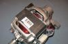
The motor is removed from an obsolete or faulty motorcycle. When choosing an engine, preference is given to two-stroke engines, but this does not mean that four-stroke engines are not used when creating a walk-behind tractor. A suitable option is the motor removed from the IZH PLANET motorcycle.
The transmission in motoblocks is used in several types:
- gear (standard tractor transmission);
- gear-worm;
- belt-toothed-chain;
- hydrostatic (a new, expensive technical device that has recently appeared on the market).

The control unit consists of a set of levers that change speeds, a button that increases or decreases the supply of fuel to the engine, brakes.
It is required that the structure is equipped with an aggregation system, which is an important structural element, connecting a home-made walk-behind tractor and created for it. Therefore, the bracket must be firmly attached to the structural frame and equipped with a power distribution device when the load on it increases.
Drawings of homemade motoblocks


Diagram of a walk-behind tractor based on the Minsk motorcycle

Drawing of a walk-behind tractor based on the Voskhod-3M motorcycle

Drawing of a walk-behind tractor based on a motor scooter
Assembly tools
Do-it-yourself assembly of technical units will require special skills and an understanding of the basics of mechanical engineering. Special equipment required:
- welding machine;
- angle grinder;
- drill;
- a set of keys;
- screwdrivers.
Among other things, bolts, nuts and screws are needed to attach the fixtures to the frame of the future walk-behind tractor.
Making a walk-behind tractor

We start making a walk-behind tractor:
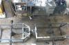
- Assembling the frame: we use a welding machine, it is advisable to use solid metal. We make the structure rigid. The frame design consists of two side members, the rear ends need to be bent upward, and the front ends must be welded together. We attach a control unit with levers to the back. We connect the spars to each other with transverse strips. The front bar will act as a stand for the transmission and battery.
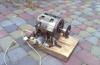
- The motor mount is made in the form of a slide, brackets are welded to the sides, and a water pipe with a diameter of 42 mm is welded to the center. A transverse arc is attached to the middle of the formed sled, which has holes for attaching the engine and the base of the frame. A place is made in the front cross member of the frame for the installation of a tension chain, which ensures the operation of the gearbox.
- Installing a gearbox is an important element in making a homemade walk-behind tractor. The gearbox converts the torque energy into lower speeds. Usually the gearbox is installed between the engine and the wheels. There are options for home-made walk-behind tractors, when the gearbox can be used not only for the movement of the walk-behind tractor, but also for the operation of a drill, cutter, etc.
- We equip the engine with air cooling, we use an electric motor designed for 12 volts.
- We put wheels not exceeding 10 inches. Splined axle shafts transmit torque to the wheels. To improve the grip of the wheels on the ground, you can install a special tire made of wire or chains - i.e. do.
- We install the exhaust system, which remains unchanged. Despite the fact that it is possible to install an exhaust exhaust removed from a motorcycle, you can make an exhaust with your own hands. You will need a pipe from which the branch pipe will be made, and muffler banks. The adapter between the pipe and the muffler must be made by a turner; it is impossible to make this attachment unit on your own.
- We prepare a place for a fuel tank, which you can make yourself: any plastic canister with a capacity of at least 5 liters will do. A hole is made in the canister and a special hose is removed through which the fuel will be transported.
- We connect the units and assemblies to each other and start the walk-behind tractor.
Using all the above tips, you can independently assemble a walk-behind tractor in a fairly short time, using only available materials and spending a small amount of money.
You will also be interested in:

Lancer or WRX, Astra or Golf, CHR or Juke? Questions for which there is no correct answer ...
A morally outdated or outdated household washing machine contains in its ...
It was built for fishing trips, picking berries and mushrooms. The author tried to use ...

The steering wheel braid is very popular and is often purchased as an accessory for ...
Looking at an old washing machine, any housewife dreams of replacing it with a new one as soon as possible ...

