


/ steel rope, characteristics of steel ropes
Steel ropes - the main load-carrying element of most lifting, transport, road construction, earthmoving machines and mechanisms, which are one of the most common types of hardware and are widely used in a wide variety of industries: coal, mining, oil and gas production and processing, transport and agricultural engineering , construction industry, sea, river transport, etc.
Our range of products includes: steel crane ropes, cargo ropes for elevators, for hoists, hoisting ropes for mine installations, for excavators, traction ropes for overhead roads and cable cranes, for skip hoists for blast furnaces, for ship lifting devices, for standing rigging of ships, spiral, mooring and towing, marine, for hoists, cranes and winches, etc.
We cut off a steel rope of any length, we complete orders with a non-standard length.
Steel ropes are a complex and demanding type of wire products. They have a large number of types and designs and differ in the shape of the cross-section of both the rope itself and its elements, as well as in the physical and mechanical characteristics of the wires and cores.
The core in the steel rope supports the strands, gives the rope flexibility and retains lubricant. It can be metallic as a single strand or organic single and double strands.


The main requirement when installing the rope is to prevent it from unwinding. To do this, it is necessary: \u200b\u200bto put the drum with the rope on the unwinding device so that the axis of the drum is in a horizontal position. The coiled end of the rope must come off the bottom or top of the drum, which must be slowed down during the coiling of the rope. The distance between the drums must be at least 300 rope diameters. During the installation process, the rope should undergo a minimum number of bends, especially alternating ones.


Surface density of zinc steel ropes.
| Nominal diameter, mm | Surface density of zinc, g / m2, not less, for wires of groups | ||
|---|---|---|---|
| FROM | F | Coolant | |
| 0.20 to 0.24 | 15 | 20 | 30 |
| \u003e 0.24 to 0.32 | 20 | 25 | 45 |
| \u003e 0.32 to 0.38 | 20 | 25 | 60 |
| \u003e 0.38 to 0.45 | 30 | 40 | 75 |
| \u003e 0.45 to 0.55 | 35 | 40 | 90 |
| \u003e 0.55 to 0.65 | 40 | 50 | 110 |
| \u003e 0.65 to 0.75 | 40 | 60 | 120 |
| \u003e 0.75 to 0.95 | 50 | 70 | 130 |
| \u003e 0.95 to 1.15 | 60 | 80 | 150 |
| \u003e 1.15 to 1.40 | 60 | 90 | 165 |
| \u003e 1.40 to 1.80 | 70 | 100 | 180 |
| \u003e 1.80 to 2.40 | 80 | 110 | 205 |
| \u003e 2.40 to 3.00 | 90 | 125 | 230 |
Unwinding of steel ropes from coils and drums of winches is carried out so that the ropes are always in a taut condition.
It is not permissible to unwind the rope from the drum, throwing the rings to the ground, since during its subsequent stretching, bends in the form of loops are formed on the rope.
Otherwise, the bends remain and significantly weaken the cable.
Place the coil on the ground and unwind the rope evenly, in a straight line, making sure that the rope is not contaminated with soil, metal chips, moisture and other harmful substances (Fig. 1). The coil can be placed on the rotary unwinder and pulled on the outer end of the rope while rotating the coil.


Never unwind the rope from a stationary coil, as this can lead to twisting of the rope and the formation of loops, which will significantly reduce the performance of the rope (fig. 2). Pay attention to the formation of loops.
If it is necessary to cut the rope into separate segments along a given length, it must be tied with knitting wire to the right and left of the felling site.
The direction of winding (turns) of the wire should be taken opposite to the direction of the twisting of the rope so that when the rope is unwound, the bandage tends to be compacted.
Methods and sequence of rope dressing operations, number and width of dressings.
| Rope diameter, mm | Number of dressings | Dressing length, mm | Distance between dressings, mm | |
| Organic core cross-lay ropes | Multi-strand single-sided lay ropes without organic core | |||
| Up to 15 | 2 | 3 | 15 | 25 |
| 15-24 | 3 | 3 | 25 | 50 |
| 25-30 | 3 | 4 | 40 | 50 |
| 31-44 | 3 | 4 | 50 | 50 |
Pass the shaft through the axial hole of the drum and place it on a support that allows the drum to rotate and slow down its rotation to avoid rope run-up. In multilayer winding, it is necessary to place the drum on a device that will provide the possibility of the return tension of the rope during its rewinding from the transport drum to the drum of the lifting installation. This will help ensure that the bottom turns are tightly wrapped around the drum (Figure 3).

The deviation angle should not exceed 1.5 ° in the case of using a smooth drum and 2.5 ° when using a drum with a screw thread, in order to ensure minimal lateral wear of the rope when rubbing against an adjacent turn in the case of a smooth drum, and against the side surface of a cut grooves in the case of using a drum with a screw thread.
Protective rope lubricants.
Great importance is attached to the choice of the type of rope lubrication and the methods of its application during the production process, since the reliability of the rope operation and the possibility of using its technical resource, etc., largely depend on this.
The lubricant is designed not only to protect the metal from corrosion, but also to ensure long-term preservation of the organic core in the rope, to reduce friction and wear of both internal and external wires when the rope is operating on blocks.
Packing of ropes.
The length of the rope is set by the consumer. The permissible length deviation should be no more than for ropes of length:
- less than 400 m + 5%
- more than 400 m + 20 m for every 1000 m or part thereof
In the absence of an indication of the length, the rope is made with a length of at least 200 m. Ropes with a length of less than 200 m are supplied as agreed with the consumer. If a multiple or assembly length is indicated, and the rope is made with a total length, then the manufacturer applies wire ties to the indicated lengths.
Ropes are wound on wooden drums in accordance with GOST 11127-78 or metal drums, as well as on return drums using them in the prescribed manner, or in coils.
- outer diameter no more than 1200 mm.
- coil height no more than 800 mm.
- the inner diameter of the coil must be at least 15 times the nominal rope diameter.
Steel ropes are supplied wound on wooden drums, sheathed with wooden planks around the circumference.
| GOST rope | Rope type | The ratio of the drum diameter to the rope diameter | |
|---|---|---|---|
| Recommended | Minimum allowable | ||
| GOST 2688-80 | LK-R | 32 | 27 |
| GOST 3077-80 | LK-O | 36 | 31 |
| GOST 7665-80 | LK-Z | 41 | 26 |
| GOST 16853-88 | LK-RO | 40 | 23 |
| GOST 7668-80 | LK-RO | 28 | 22 |
| GOST 3079-80 | TLK-O | 27 | 22 |
| GOST 3069-80 | LK-O | 70 | 40 |
| GOST 3066-80 | LK-O | 75 | 44 |
| GOST 14954-80 | LK-R | 34 | 29 |
| GOST 7667-80 | LK-Z | 42 | 28 |
| GOST 16853-88 | LK-RO | 41 | 25 |
| GOST 7669-80 | LK-RO | 35 | 23 |
| GOST 3083-80 | LK-O | 40 | 28 |
| GOST 3081-80 | LK-O | 42 | 37 |
| GOST 3070-88 | TC | 34 | 29 |
| GOST 3071-88 | TC | 21 | 18 |
| GOST 3067-88 | TC | 40 | 34 |
| GOST 3068-88 | TC | 25 | 21 |
Truck cranes KS-5579.22 are designed to perform various loading and unloading and construction and installation works at dispersed facilities. Hoisting machines of this model are distinguished by their reliability, quality, productivity, high speed performance, as well as throughput and the ability to be cost-effective in almost any weather and climatic conditions... In the construction of truck cranes KS-5579.22 there are a number of features that distinguish this machine from analogues of other production.
One of distinctive features of the KS-5579.22 truck crane is the ability to work in a circular zone of 360 degrees, which allows you to minimize the number of crane permutations during operation. With such a large area, the area of \u200b\u200bthe served space KS-5579.22 is almost 2000 m2. These properties indicate the high performance of the crane and allow the most rational use of its capabilities. Another difference is the design feature of the outriggers: the support circuit is located crosswise and is equipped with hydraulic drives, which makes it possible to work in confined conditions. Undoubtedly, all the above features incline the choice in favor of buying a KS-5579.22 truck crane.
Crane installation KS-5579.22 chassis mounted domestic production KAMAZ-53229 brand with a 6x4 wheel arrangement. The chassis is equipped with a powerful diesel turbo engine KamAZ-740.31-240, which meets all safety standards and requirements, including the content of substances in the Euro-3 exhaust gases. The chassis engine produces an operating power of 240 horse power... The chassis allows you to efficiently use the KS-5579.22 truck crane in hard-to-reach places due to the condition of the access roads. Including during the laying of gas and oil pipelines, the development of mineral deposits. Meanwhile, this model can work in urban areas, which is facilitated by the compactness of the chassis and crane installation.
The KS-5579.22 truck crane is equipped with a three-section telescopic hydraulic boom, which allows it to deliver goods to a height of about 25 meters, with the appropriate equipment this figure increases to 37 meters. It is possible to equip the KS-5579.22 truck crane with a lattice boom extension, which is designed to increase the underfloor space and the height of lifting loads. The gooseneck can be mounted at an angle of 0 ... 15 ... 30 degrees. It is noteworthy that there is the possibility of telescoping the boom with a load suspended on a hook weighing up to 6000 kg, which allows the truck crane to perform some special tasks, for example, to deliver the load to a hard-to-reach place or carry it among the mounted metal structures. With a lifting capacity of 32 tons, the maximum load moment of the truck crane KS-5579.22 is 105 tm, which is excellent result... The boom in the transport position is placed on a rack, and the hook clip is placed in a niche behind the cab, this operation is carried out without the help of a slinger. All these features leave no doubt about buying a mobile crane KS-5579.22.
In our company sale of truck cranes KS-5579.22 carried out in comparatively low prices, the technique is available to most interested citizens. If you decide to buy a KS-5579.22 truck crane, you need to contact us by phone or e-mail, the numbers and addresses of which are in the "Contacts" section.
Often, customers of cable and wire products are faced with the task of determining the length of the cable wound on a drum and choosing the appropriate type of transport for its delivery. We take into account the needs of our customers and offer modern ways of solving problems.
The online service "Calculation of the length of the cable on the drum" is an interactive calculator with which you can independently calculate the length of the cable / wire. We guarantee that the service will become a useful helper for your work, thanks to which you will save not only your time, but also money.
How to determine the length of a cable / wire on a drum without unwinding
- To make the calculation, enter the brand of the cable with the cross-section in the appropriate field on the service page (just enter the first characters, the service will offer options automatically).
- Select the cable brand of interest with the cross section. Done!
For convenience, the results on request are generated and presented in the form of a table.
The service information is for reference and informational nature and is based on the data of the manufacturers. The minimum calculation error allowed by the manufacturer is possible.
I want this service on my website
Online service code for your website:
Our online services are constantly being improved and updated to provide customers with accurate and up-to-date information. The information is for reference and informational purposes only.
Set of sliding plates, sliders of the Motovilikha truck crane KS-5579, KS-5579.22
Sliders (slide plates) designed to complete the boom of a telescopic truck crane Motovilikha KS-5579, KS-5579.22 produced by LLC "Plant SDM", Perm.
are installed in the root section of the boom and are used to smoothly extend / retract the boom sections. The slider is attached to a metal shoe. The main reason for the failure of sliders is wear. It manifests itself with uneven, jerky movement of the boom sections .
Sliding plates (sliders) of the boom of a telescopic truck crane,allow easy movement of the extendable boom section at the base of the metal structure,
this eliminates the friction of the boom sections against each other.Fits on the boom section shoes at the front and rear. When worn out, they require replacement.
As a rule, the reason for replacing the sliders (sliding plates) of the boom equipment of a truck crane is their wear, as a result of which the extension and retraction of the boom sections occurs unevenly, with jerks.
Sliding plates (sliders) of the truck crane have high antifriction properties and can be made of bronze or polyamide.
Sliding plates (sliders) of the truck crane " Motovilikha "KS-5579, KS-5579.22 usually made of glass-filled polyamide"ARKAIM-1006-block" TU 219140-001-325315614-02 , since this material is much cheaper than bronze.
Truck crane slidersthat we offer - gives a significant economic effect in many respects: the overhaul interval of the equipment increases, the wear of the mating parts decreases, the noise is significantly reduced, this material is 7-8 times lighter than bronze and lends itself well to machining, in many nodes a flow line is suitable as a lubricant water (instead of fuels and lubricants).
Slide plates (sliders) telescopic sections reduce friction and smooth running when extending and retracting boom sections, as well as to eliminate gaps between sections, the design provides for installation crawlers between the inner and outer walls of the sections. Fixed sliders are installed in the head lower parts of the first, second and third boom sections, and movable ones - on the upper rear parts of the second, third and fourth sections.
When moved, the upper boom section rests on slide plates mounted at the lower front of the base, and at the rear on slide plates mounted at the top of the upper boom section
During assembly, the gaps between the sliders and the surface of the sections are adjusted by installing spacers, and spacers are also installed additionally as the sliders (sliding bearings) wear out during operation.
Set of sliders (slide plates) and boom shoes of a telescopic truck crane
Motovilikha KS-5579
Set of sliders and shoes for telescopic crane boom
consists of the following items:
Sliding plates (sliders) of the KS-5579 truck crane produced by LLC "Plant SDM", Perm
|
P / p No. |
Name |
Number of pieces |
|
1 |
|
6 |
|
2 |
Sliding support SMZ- 3.400.00.12 |
2 |
|
3 |
Sliding support SMZ- 3.400.00.12-01 |
2 |
|
4 |
|
2 |
|
5 |
|
2 |
|
6 |
Sliding support SMZ- 3.400.00.21 |
2 |
|
7 |
Sliding support SMZ- 3.400.00.24 |
2 |
|
8 |
Sliding support SMZ- 3.430.00.03 |
2 |
|
9 |
|
2 |
Sliding plates (sliders) of the KS-5579.22 truck crane produced by LLC "Plant SDM", Perm
|
P / p No. |
Name |
Number of pieces |
|
1 |
Sliding support SMZ- 3.400.00.10 |
6 |
|
2 |
Sliding support SMZ-5.400.00.10 |
2 |
|
3 |
Sliding support SMZ- 3.400.00.18 |
2 |
|
4 |
Sliding support SMZ- 5.400.00.08-01 |
1 |
|
5 |
Sliding support SMZ-5.400.00.08 |
1 |
|
6 |
Sliding support SMZ- 5.400.00.05-01 |
2 |
|
7 |
Sliding support SMZ- 3.400.00.14 |
2 |
|
8 |
Sliding support SMZ-5.400.00.05 |
2 |
|
9 |
Sliding support SMZ- 3.430.00.05 |
2 |
|
10. |
Sliding support-SMZ-5.400.00.03 |
2 |
Slide plates (sliders)truck crane
Installed in the root section of the boom and used to smoothly extend / retract the boom sections. The slider is attached to a metal shoe. The main reason for the failure of sliders is wear. It manifests itself with an uneven, jerky movement of the boom sections.The slide support (slide plate) is designed for decrease in strength
friction on boom sections of truck cranes ... To prevent lateral displacement, in the front part of the sections, side stops are provided with the ability to adjust the gap, in the rear of the sections, side plates are installed. On some models of cranes there is a mechanism for locking the sections in the extended state.Polyamide - an antifrictional self-lubricating composite material, close to metals in mechanical properties, and to polymers in terms of friction conditions, is used for the manufacture of parts of friction and rotation units operating both when lubricated with oils, fresh water, and without lubrication. Polyamide products are lighter in weight, have excellent antifriction properties, high impact resistance, wear resistance, corrosion resistance and a long service life.
Among the advantages of using polyamide sliding plates (crane sliders)
· Reducing operating noise
· Weight reduction (LAMIGAMID density ρ \u003d 1.15 g / cm 3)
· High wear resistance
· High corrosion resistance
· Economical operation
· No maintenance required
· High mechanical strength, rigidity, hardness and toughness
· Good fatigue strength
· High mechanical damping capacity
· Good sliding properties
· Very high wear resistance
· Good insulating properties
· Good workability
· High resistance to high radiation energy (gamma and X-rays)
Our company specializes in the development and production of various products from this modern material. Experts take an active part in the study of operating conditions, in industrial testing of products and help find the necessary technical solutions until the full implementation of parts into operation
Set of sliding plates, sliders of the mobile crane Motovilikha KS-5579, KS-5579.22 Sliders (slide plates) are designed to complete the boom of the telescopic truck crane Motovilikha KS-5579, KS-5579.22 manufactured by LLC Plant SDM, Perm. Motovilikha "KS-5579, KS-5579.22 are installed in the root section of the boom and are used for smooth extension / retraction of the boom sections. The slider is attached to a metal shoe. The main reason for the exit ..Mobile cranes
Metallurgical cranes

Tower cranes

1. Transportation and storage of ropes.
1.1. When the rope is delivered to the place of storage or hitch, the drum must be removed from vehicle lifting mechanisms in such a way as to prevent damage to the rope and drum. It is forbidden to throw the drum with the rope from the vehicle or to remove it in ways that damage it or break the layer of conservation grease.

1.2. The ropes received for storage must be inspected; Lubricate rope sections exposed during transportation and handling. In this case, the lubricant must be compatible with the type of lubricant applied during the manufacture of the ropes. Measure the diameter of the rope.

1.3. During long-term storage, the ropes should be visible along the outer layer and lubricated at least after 6 months.
1.4. Ropes should be stored in ventilated rooms or under a canopy in conditions that exclude the ingress of atmospheric precipitation, away from vapors and corrosive atmosphere. The axis of the drum should be parallel to the floor on which the drum is installed. Do not place drums directly on the ground. They must be installed on special decks, planks or racks.

2. Hitching up the ropes.
2.1. Hitching of ropes should be carried out by a team of workers who are familiar with the hitching instructions developed and approved in accordance with the established procedure for this enterprise.
2.2. When carrying out work on hitching or replacing the rope, it is necessary to ensure measures to prevent the ingress of abrasive and contaminating materials onto the rope surface. For this, work is recommended to be carried out on a special stand made of boards.

2.3. Selection of the direction of lay when winding on a drum. The rope is wound on a drum along a helical line, and at the same time undergoes bending, contact and torsion deformations that cause it to rotate around an axis. It is necessary to select such a lay direction in which, during the winding process, the rope is twisted before being laid on the drum; this will help maintain the tightness of the lay.

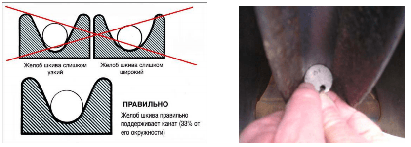
2.4. Hitching a new rope should be preceded by a thorough check of the condition of the streams of the system blocks and the grooves of the drums of the corresponding winch. Stream diameter should be 5% -7.5%
larger than the nominal rope diameter. Too narrow block streams pinch and deform the rope, compromising its structural integrity, which can lead to premature exit rope out of order. Too large block grooves create insufficient support for the rope, leading to increased contact pressures and premature rupture of the rope wires.
2.5. Spiral cutting is recommended on winches with single-layer winding on the drum. For multilayer winding, parallel cutting or one of the typical systems (eg Lebus cutting, etc.) is required. In all cases, the appropriate thread pitch, gap and groove depth are of prime importance to obtain good rope running times.
for auxiliary winches, the dimensions of the rope winding elements must comply with the requirements of GOST 3241: the diameter of the drum neck must be at least 15 nominal rope diameters.
2.7. Before unwinding, the transport drum with the rope must be installed on an unwinding device that provides a horizontal position of the drum axis and is equipped with
a braking device to create the required rope tension and to avoid the formation of loops and creases. Slack or uneven rope winding leads to excessive wear, crushing and deformation of the rope.


2.8. The drum in the unwinding device must be installed in such a way that the formation of alternating kinks is excluded, for example, for a winch drum with top winding of a rope, it is necessary to unwind the rope from the transport drum from above.

2.9. In the case of unwinding a rope from the coil of a pre-cut measured piece, it must be installed on a rotary unwinder and pulled by the outer end of the rope, rotating the coil.
Do not unwind the rope from a stationary coil, as this can lead to twisting of the rope and the formation of loops, which during operation can lead to the formation of structural defects on the rope and a significant reduction in the service life of the rope.

2.10. The unwinding device must be installed in such a way that the deviation angle does not exceed 1.5 degrees in case of using a smooth drum and 2.5 ° when using a drum with a screw thread, in order to ensure minimal lateral wear of the rope when rubbing against an adjacent coil in the case of a smooth drum, and the side surface of the cut groove in the case of a helical drum.

At the pulley
If there is a deviation angle when the rope enters the pulley, then the rope first contacts the pulley flange. As it passes through the pulley, the rope goes down the pulley until it descends to the bottom of the groove. During this process, even under tension, the rope will rotate and slide. As a result of rotation, the rope is twisted, i.e. twisting is formed in the rope or the twist comes out of it, shortening or lengthening the lay step of the outer layer of the strands. As the deviation angle increases, the torsion volume increases. To reduce this volume to an acceptable level, the deviation angle should be limited to 2.5 ° for grooved drums and 1.5 ° for smooth drums. When using non-rotating, low-rotating ropes and parallel twisted ropes (i.e. ropes in which
strands and core are twisted into a rope in one operation) the deviation angle must be limited to 1.5 °. However, for some cranes and hoisting systems, for practical reasons it is not always possible to adhere to these general guidelines affecting rope life.
At the drum
without returning to the drum.

In this situation, the problem can be mitigated by installing a "breaker" or by increasing the deviation angle by installing a pulley or winding mechanism. If the rope is allowed to pile up, then, ultimately, it will roll away from the flange and create an shock load, both in the rope and in the structure of the mechanism, which is undesirable and unsafe for operation. Too large deviation angles will
 return the rope to the drum prematurely, and create gaps between the rope turns near the flanges, as well as increase the pressure on the rope at the intersection points. Even where there is spiral groove, large deviation angles will inevitably lead to localized areas of mechanical damage, since the wires "cling" to each other. This phenomenon is often referred to as “interference”, but it can be reduced by choosing a one-way lay rope if re-supplying allows. The effect of "interference" can also be reduced by using a compressed strand rope that has a much smoother surface than conventional ropes. Floating pulleys or specially designed compensating devices can also be used to reduce the effect of the deviation angle.
2.10. If it is necessary to cut the rope, at least three dressings of a length equal to two or three diameters of the rope must be applied to it on each side of the cut from a soft wire. Cut the rope by electric welding with simultaneous welding of the end.

2.11. For hanging a new rope using the old one, the following types of ends and connections are recommended:
tapering

looping


non-twisting fit for standard ropes
termination for standard and non-rotating ropes with torsion swivel
for rope with loop
"Chinese stocking"
CAN'T CONNECT ROPE WITH RIGHT SWING- WITH ROPE WITH LEFT SWING

2.12 Types of terminations:
Steel rope casting coupling


| Step 1 | Step2 | Step3 |
A method of embedding a steel rope into a sleeve for casting with a low-melting alloy or polymer.
Wedge clamp.


Method of embedding a steel rope in a wedge sleeve
Steel rope crimping sleeve
 |
 |
| Open | Closed |
Types of steel couplings for crimping steel rope

3. Running in and tightening of ropes
3.1. Since in the initial period of operation there is a constructive lengthening of the rope and redistribution of stresses in the rope, then after the new rope is hinged up, it is necessary to run and tighten it. Running-in and tightening of the rope should be carried out simultaneously, starting at a low speed and load, with a further increase in load and speed. This will gradually stabilize the internal stresses in the rope and allow it to adapt to the working conditions.
1. Running in and tightening the rope without load:
- ƒ with a minimum speed, 2-3 cycles are performed (the cycle includes winding the rope on the winch drum and winding the rope during the return stroke);
- with the nominal speed of movement, 2-3 cycles are carried out.
2. Running in and tightening the rope at a load of 1/4
- with rated speed, 2-3 cycles are performed.
3. Running in and tightening the rope with a load of 1/2:
- 2-3 cycles are performed at the minimum speed;
- ƒ 2-3 cycles are performed at rated speed.
4. Running in and tightening the rope at full load:
- ƒ 2-3 cycles are performed at minimum speed;
- ƒ further work is performed at full load at rated speed.
4. Operation of ropes
4.1. After hitching, running in and tightening the ropes, inspect the ropes, attachment points and, in the absence of deviations, carry out their operation as usual.
4.2. The ends of the outer wires cut off during operation must be removed from the rope by bending them back and forth with pliers until the wires break deep in
the gap between the two outer strands.

4.3. .The rope should be lubricated with grease at regular intervals during operation. Service lubricant must be compatible with the type of lubricant applied during manufacture, which is indicated on the rope certificate.

- Before applying a fresh coat of lubricant to the rope, it must be cleaned of foreign elements such as dust, sand, pieces of rock, etc.
- The type and method of applying the lubricant should ensure that all wires in the rope are evenly coated with a thin layer.
- Do not use uncleaned or used lubricants. they can be contaminated with caked particles or acids, which can also have a negative effect on the rope
4.4. It is necessary to monitor the condition of the grooves on the drums and blocks. The operation of the rope with worn-out streams leads to a decrease in the contact area and, as a result, to deformation and
violation of the rope structure. During the operation of the crane, as well as during its transportation and installation, rope-block systems
may have the following malfunctions, falling out of the rope from the block stream; jamming of ropes on blocks; twisting the cargo rope; chafing of ropes; breaks of wires, strands and rope
generally; wear of the stream and flanges of blocks; breakage of blocks. Falling out of a rope from a stream of blocks leads to rubbing it against the sharp edges of metal structures, breaking and falling of a load or an arrow. The rope can fall out due to the fact that the guardrails are bent, the rope is stretched obliquely in relation to the block, or it is incorrectly stored. In the latter case, the rope wedges between the flange and the fence and bends it.

Jamming of the ropes on the blocks can occur if the bearings of the block are jammed or the rope touches the guard of the block. In view of the fact that these malfunctions lead to intensive wear of the stream of blocks and the rope, they must be immediately eliminated. If the guardrail is bent, it should be straightened or unbent, ensuring free passage of the rope. The block bearings must be cleaned and filled with clean grease or replaced with new ones. If the lubrication holes are clogged, they must be cleaned.


The wear of the grooves and flanges, blocks, as a rule, occurs if the bearings of the block are seized or the rope is pulled obliquely. When the bearings are poorly lubricated and they are seized, the rope slides over the block, which in an abrasive environment (dust, sand) leads to a rapid development of a stream or block flanges. Blocks are generated especially quickly
at a small angle of coverage by the rope, since the pressure force of the rope is insufficient for the rotation of the block. In the oblique direction of the rope, one-sided wear of the side surface of the flanges of the blocks occurs. To prevent this, work should be avoided, causing oblique tension of the rope, pulling the load, lifting the hook block to the limit.

4.5. The twisting of the cargo rope is observed with a long suspension length. This usually occurs due to the fact that the rope was unwound from the coil incorrectly during its reeving on blocks or when the rope is very stiff. Failure can be prevented by untwisting the rope or using an anti-twist device.
Chafing of the ropes occurs, as a rule, when they are incorrect
stockpile. In this case, during crane operation, the ropes touch as
each other and metal structures. The ropes also fray when an attempt is made to lift the load while the rope is twisted. Since crane operation with frayed rope can lead to the fall of the load or the boom, it is necessary to prevent this malfunction. To do this, you need to spread the ropes at a distance at which they cannot touch the metal structure and touch each other.
4.6. Defects of steel ropes during operation
 |
wire buckling |
 |
core bulging |
 |
local diameter reduction |
 |
swelling of a strand |
 |
localized wear |
 |
kink formation |
 |
formation of defects such as a wave or a spin in the ropes |
 |
basket-like deformation |
 |
external wear |
 |
surface corrosion |
 |
bursts of wires |
 |
buckling of the rope core |
 |
local increase in rope diameter |
 |
a loop |
 |
significant wear of wires rope |
 |
strong internal corrosion. |
ATTACHMENT 1

Minimum coefficients for choosing the diameters of the drum (h1), block (h2) and equalizing block (h3).
|
Classification group |
Diameter selection factors | ||
| h1 | h2 | h3 | |
| M1 | 11,2 | 12,5 | 11,2 |
| M2 | 12,5 | 14,0 | 12,5 |
| M3 | 14,0 | 16,0 | 12,5 |
| M4 | 16,0 | 18,0 | 14,0 |
| M5 | 18,0 | 20,0 | 14,0 |
| M6 | 20,0 | 22,4 | 16,0 |
| M7 | 22,4 | 25,0 | 16,0 |
| М8 | 25,0 | 28,0 | 18,0 |
The minimum diameters of drums, blocks and equalizing blocks bent by steel ropes are determined by the formulas:
D1 \u003d h1 * d; D2 \u003d h2 * d; D3 \u003d h3 * d. where d is the diameter of the rope, mm D1, D2, D3 are the diameters, respectively, of the drum, block and equalizing block along the centerline of the wound rope, mm h1, h2, h3 are the coefficients for choosing the diameters of the drum, block and equalizing block, respectively (according to Table 1) ...
One-sided nney
* D - drum diameter, mm;
d - rope diameter, mm.
You will also be interested in:

To change the oil in the variator, you need a little: First of all, you need the oil itself, for my ...

The Skoda automobile concern is one of the oldest in the world. We remind you that in 2000 ...

Through the site service, you can find out data from the STS. These include: sts number, brand, model, ...

Audi Q5 2.0 TFSI quattro / Audi Ku5, 5dv off-road vehicle, 211 hp, 7 automatic transmission, 2008 - 2012 -...

Test drive What is permanent four-wheel drive? And then why on the field the lever "lock ...

