


Welcome!
This part connects the alternator pulley to the crankshaft pulley and the water pump pulley on classic models. On front-wheel drive vehicles, the pump pulley links the timing belt. A break in the alternator belt on the classic will cause poorly working devices, because the energy will come only from the battery, respectively, with a poor charge, the devices will junk. On the contrary, if the battery is powerful and sufficiently charged, then for some time the devices will not go out and you may not even notice that the belt has broken. And here you need to remember about the pump and pay attention to it, since the belt connects it, then the gap will lead to the cessation of the circulation of the coolant in the system and the car will start to get very hot.
Note!
you will need the following tools: a mounting spade (a comfortable thick stick or a small metal scrap will do), wrenches will be needed for "17" and "19".
Belt location
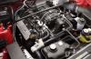
Located at the front of the vehicle. In the photo, the red arrow shows the radiator of the cooling system and the bar on which the battery is located (now removed). The belt connecting the three pulleys is indicated in the photo with a blue arrow.
When to change the belt?
The main reason is wear: various kinds of cracks, worn edges, worn teeth. We do not recommend tightening when replacing the belt, otherwise a rupture will lead to overheating of the engine and even boiling during extreme heat. The battery will quickly discharge in the absence of support from the generator, which will stop spinning and give off energy.
Note!
Have you ever heard the whistle of a car? The sound is made by the timing belt, it arises for various reasons:
- severe wear and tear often leads to whistling;
- ingress of water or any liquid on it (for example, coolant enters the belt when worn out cooling system pipes are leaking. Inspection of the belt and pulleys for moisture will help to identify the problem);
- weak belt tension (adjustment will come to the rescue, read below);
- low quality belt, sometimes oak belt is straight (by the way, it hardens in frost).
Most cars in the winter time of the year emit a whistle when starting the engine, and a heated car no longer whistles - a sign of a hardened belt.
The video below can save you in an emergency: if a belt suddenly breaks on the road, and there is no spare, a regular belt or tie will come to your aid! Look in detail in the video and shake it off, you never know, everything in life will come in handy.
We change the belt for a VAZ 2101-VAZ 2107
Withdrawal
Note!
Removing the battery will make it easier to access the belt. The process is described in the article: "Replacing the battery in cars".
Assess the appearance of the belt. If the condition is not bad, check the tension, tighten it if necessary. It's easy to check: squeeze the belt with your fingers with a force of 10 kg anywhere. Either in place "A" the distance to which the belt should bend will be 10-15 mm, or in place "B" 12-17 mm (see picture).
Note!
It is more convenient to squeeze and check the deflection at point "A". Any deviation from the norm requires a belt tightening. Remember, do not remove the belt from the pulleys unless you intend to replace!
Move to the lower car part and unscrew the lower generator nut one turn (see small photo), get out from under the car and go to the engine compartment. Loosen the generator upper mounting nut by one or two turns (red arrow in the photo), an extension cord with a universal joint and a union head (tools are indicated by a blue arrow) will help you. Loosen through the battery mounting bar.
Note!
The upper nut that secures the generator to the bar is twisted differently for everyone, so as soon as you feel that the nut goes easily (see, do not turn it out completely), then immediately stop unscrewing!
We proceed directly to changing the belt. Move the generator to the engine with your hands and remove the belt. If you just need to adjust, then insert a mounting blade between the engine and between the generator itself (see photo below), and using the blade as a lever, move the generator away from the engine. Holding the spade in this position, tighten the upper nut securing the generator to the bar and the lower one too. Release the paddle and remove it, check the belt tension and, if necessary, repeat the operation (if the tension is not within the norm).
Installation
First, install the belt on the crankshaft pulley. In the image above, see the pulley indicated by the number 3, the alternator pulley by the number 2 and the pump pulley by the number 1. Move the alternator to the end of the engine, if it is shifted, but the belt still does not install, then gently turn the pump pulley (upper) by hand, or in the extreme In case, ask the assistant to use the crooked starter to turn the pulley a little, and at this time you put the belt on the upper pulley of the pump.
Note!
We attach a video about adjusting the belt tension, enjoy your viewing!
5.3.7. Heater blower motor WARNING Vehicles are equipped with safety systems (SRS), which include airbags and seat belt pretensioners. Before working around the shock sensors, dashboard and steering column, first disconnect the negative and then the positive terminals from the battery and wait 2 minutes. This will prevent unauthorized deployment of the airbags and the deployment of the seat belt pretensioners, which could cause injury. Turn off the ignition and disconnect ...
Replacement of the power steering pump UAZ 3163 /
8.5.5. Replacing the power steering pump You will need: keys "22", "27", a flat-blade screwdriver. 1. Remove the power steering pump drive belt (see "Replacing the power steering pump drive belt and the cooling fan drive viscous clutch"). 2. Unscrew the pressure hose securing bolt ... 3. ... and disconnect the discharge hose from the pump. Note The connection of the pressure hose to the power steering pump is sealed with copper washers. Replace heavily compressed washers with new ...
Replacement of the power steering pump UAZ 31519 /
8.5.7. Replacing the power steering pump You will need: keys "17", "22". 1. Remove the power steering pump drive belt (see "Replacing the power steering pump drive belt and cooling fan pulley"). 2. Unscrew the pressure hose fastening bolt… 3.… and disconnect the hose from the pump. Note On some cars, the delivery hose has a tube that is attached with a nut to the pump union. 4. Unscrew the bolt-union of the suction wagon ...
Kia Sportage Cooling Fan Drive Bearing Replacement /
Replacement of the bearing of the cooling system fan drive PERFORMANCE ORDER Remove the alternator drive belt. Remove the fan impeller, then remove the fan drive pulley from the bearing assembly mounting flange. 1 - Impeller 2 - Pulley Loosen the fasteners and remove the bearing assembly (1) from the engine block. Using a special puller and a suitable punch, use a press to dismantle the drive pulley seat flange. one ...
Replacing the coolant VAZ 1111 /
3.5. Replacing the coolant The coolant drain plug is located above the dipstick tube, and the radiator drain plug is located on the right radiator reservoir under the coolant fan switch. You will need a 13 ”wrench to drain the coolant coolant funnel Warnings Use coolants recommended by the manufacturer (see appendix). The coolant is toxic, ...
Mercedes-Benz W163 (ML Class) crankshaft front oil seal replacement /
Replacing the front crankshaft oil seal 1 - ancillary drive belt, 2 - fan diffuser, 3 - fan and viscous clutch assembly, 4 - bolt, 5 - crankshaft pulley, 6 - special device, 7 - oil seal. 1. Remove the engine trim panel. 2. Remove the fan and viscous clutch in the c6o 3. Remove the fan diffuser. 4. Remove the ancillary drive belt. 5. Remove the crankshaft pulley. 6. Remove the old crankshaft oil seal with a screwdriver. Not...
Checking the condition and replacing the timing belt - models 2.0 and 2.5 L Subaru Legacy Outback /
Checking the condition and replacing the timing belt - 2.0 and 2.5 l models Timing belt installation details 1 - Right rear timing cover 2 - Timing belt guide (only models with manual transmission) 3 - Crankshaft gear 4 - Left rear timing cover 5 - Toothed wheel of the right camshaft 6 - Intermediate roller No. 1 7 - Support bracket of the tensioner 8 - Intermediate roller No. 2 9 - Assembling the automatic ...
Replacing the coolant VAZ 2110 /
2.2. Coolant replacement GENERAL INFORMATION Warnings Change the coolant only on a cold engine. Coolant is toxic, so be careful when handling it. When starting the engine, the expansion tank cap must be closed. The coolant change is shown on the engine mod. 2111. PERFORMANCE ORDER 1. Place the car on a horizontal level surface. If the site has a slope ...
Infiniti QX4 Timing Belt Replacement /
4.6. Replacing the timing belt Do not bend or twist the belt! After removing the timing belt, do not turn the crankshaft and camshafts to avoid damage to the internal components of the engine as a result of the impact of the valves on the piston crowns! Before installing the belt, thoroughly clean all the timing gears, completely removing dirt, grease and moisture from them! The timing belt must be installed on a cold engine! Details ...
Checking the condition, removing and installing the cooling system fan Toyota Land Cruiser /
Checking the condition, removing and installing the cooling fan Avoid touching the impeller blades with your hands, tools and items of clothing. To avoid personal injury or property damage, do not start the engine with a defective fan. Do not attempt to repair broken impeller blades, replace the complete impeller! Check PERFORMANCE ORDER 1. Check the fan impeller for cracks, paying special attention to the condition of the base ...
Replacing the drive belt of the power steering pump and the fan pulley of the cooling system UAZ 31519 /
8.5.1. Replacing the drive belt of the power steering pump and the fan pulley of the cooling system You will need: keys "10" (two), "17" (one). 1. Loosen the two bolts securing the power steering pump tension plate. 2. While holding the tension bolt with a wrench, loosen the nut and lower the pump down. 3. Remove the belt. 4. Install the new belt in the reverse order of removal. ...
Replacing the drive belt of the UAZ 3163 generator /
10.4.3. Replacing the alternator drive belt You will need: keys "10", "12". 1. Remove the power steering pump drive belt (see "Replacing the power steering pump drive belt and the cooling fan drive viscous clutch"). 2. Loosen the tension roller mounting bolt two to three turns. 3. Unscrewing the adjusting bolt, loosen the belt tension ... 4. ... and remove it. 5. Install a new belt and, rotating the tension roller bolt, achieve a belt deflection of 15 mm under a load of 80 N (8 kgf), ...
Replacing the drive belt of the UAZ 31519 generator /
10.4.4. Replacing the alternator drive belt You will need: keys "10", "12". 1. Remove the power-assisted steering pump drive belt (see "Replacing the power-assisted steering pump drive belt and fan pulley"). 2. Loosen the tension roller mounting bolt two to three turns. 3. Unscrewing the adjusting bolt, loosen the belt tension ... 4. ... and remove it. 5. Install a new belt and, rotating the tension roller bolt, achieve a belt deflection of 15 mm under a load of 80 N (8 kgf) applied in the middle of the belt branch between ...
Replacement of coolant Mercedes-Benz W210 (E Class) /
Changing the coolant WARNING Burns can occur if the engine is hot. STEPS OF WORK 1. Carefully remove the cap of the expansion tank. 2. Relieve excess pressure from the cooling system. 3. Set the heating control on the dashboard to "Heiss" (hot). This opens the cooling circuit of the heating system. 4. Remove the crankcase protection. 5. Place the collection container under the radiator and the engine, on the bottom of the radiator, unscrew the drain plug (Fig. 4.45) and drain the coolant. On pcs ...
Checking the condition and replacing the water pump Nissan Maxima QX /
Checking the condition and replacing the water pump CHECKING PERFORMANCE ORDER 1. Failure of the water pump can lead to the most serious consequences, up to the complete seizure of the engine as a result of overheating. 2. There are two ways to check the correct functioning of the water pump without removing it from the engine. The defective pump must be replaced. The first is the simplest: when the engine is running, warmed up to normal operating temperature ...
Replacing the drive belt of the generator and water pump UAZ 31519 /
5.7. Replacing the drive belt of the generator and water pump You will need: keys "10", "12". 1. Remove the drive belt of the power steering pump, viscous clutch pulley and crankshaft pulley (see "Replacing the drive belt of the power steering pump and the cooling fan pulley"). 2. Loosen the idler roller mounting bolt two to three turns. 3. After unscrewing the adjusting bolt, loosen the belt tension and remove it. 4. Install a new belt; screwing in the tension roller adjusting bolt, add ...
Checking, replacing and adjusting the drive belt of the water pump and alternator Mercedes-Benz W123 /
Checking, replacing and adjusting the drive belt of the water pump and generator Every 24,000 km, check the drive belt and adjust its tension. Inspect the belt along its entire length for possible cracks and wear, and crank the engine to check the belt surfaces in contact with the pulleys. Replace the defective belt. PERFORMANCE ORDER On cars with the power steering, air conditioning system (compressor), their drive belts should be removed first. Disconnect the ground wire & ...
Mercedes-Benz W210 (E Class) fuse replacement /
Replacing the fuse SEQUENCE OF WORK 1. If you need to replace the fuse, you can use the plastic tweezers, which is included in the standard tool kit. 2. Remove the blown fuse from the contacts with tweezers. 3. Insert a new fuse of the same rating into the contacts. Make sure the contact is reliable. 4. If the new fuse immediately blows, refer to table. 9.1, whether a fuse with a smaller rating than required has been installed. 5. If everything is correct, determine the electrical connected to the circuit using the table.
To supply the electrical systems of the car with energy, each car has two power sources - a DC battery and a three-phase alternator equipped with a powerful rectifier bridge. But in order for the latter to start producing current, it must be made to spin. This is done with the engine running using a crankshaft and a belt. Often the latter requires replacement.
Belt drive: advantages and disadvantages
The alternator belt drive refers to transmissions called flexible coupling. The drive includes two pulleys - the leading one is attached to the end of the crankshaft, the driven one is mounted on the generator shaft, as well as the belt thrown over them. The transmission of torque is carried out by frictional forces.

Alternator belt types
Since different brands of passenger cars have engines of different types, they use three types of alternator belts:
- wedge-shaped (in cross-section they are trapezoidal, capable of transmitting significant forces, withstand large overloads);
- poly-wedge (wide, with longitudinal grooves, have reverse flexibility and are used to transmit rotation to several devices);
- gear (on the inner side they have transverse grooves and are endowed with the ability to accurately observe the gear ratio).
A separate belt drive of the powerful 3-phase generator of a modern passenger car is a poly-V-belt, consisting of many longitudinal V-shaped teeth located on the inner side of a flat endless base. The main condition for the stable operation of the generator belt is the mandatory presence of a tensioner. The tension roller or the generator itself acts as it.
V-ribbed belt transmission has both advantages and disadvantages.
Advantages
- small weight and small thickness allow the belt to be used in drives of motors with high speed;
- increased reverse flexibility allows you to simultaneously transfer rotation to the hydraulic booster, water pump, generator, air conditioning compressor;
- has increased resistance to cracking;
- protects the generator from shock and peak loads during engine start and stop;
- protects the generator from overload by slipping the belt in the pulleys;
- stable transmission of torque with a significant distance between the crankshaft and generator pulleys;
- simplicity of design;
- smooth and quiet operation;
- no lubrication required;
- low cost combined with a long service life.
disadvantages
- shaft ends with pulleys and thrust bearings are under the influence of decent forces arising from strong tension;
- when heavy loads occur, there is strong wear on the side surfaces due to slippage;
- service life depends on correct tension;
- the mechanism cannot work normally when oil gets on it, so protection from any kind of lubrication is required.
Alternator belt design and material

The V-belt consists of 5 layers
The product must have the following characteristics:
- high strength with significant load fluctuations;
- good wear resistance;
- the maximum coefficient of adhesion to the working surfaces of the pulleys;
- be flexible but tough.

V-ribbed belt consists of the following layers
The generator drive is made in the form of an endless flat belt, on the inner surface of which there are longitudinal wedge-shaped ribs. This design combines the elasticity of the flat and the increased traction of the V-belt. The basis is a cord reinforced layer of synthetic cords covered with a rubberized high-strength rubber fabric. This design is practically not subject to stretching.
When to change the alternator belt
Modern technologies make it possible to manufacture a generator belt so strong that it can operate reliably for a long time - several tens of thousands of mileage. Many manufacturers set a standard for the obligatory replacement of the alternator belt at 80-100 thousand kilometers. But control over the state of this important element of the generator drive should be. Common practice: Visual inspection for cracks and edge breakage when a sustained whistling sound occurs. Burrs and misalignments on the pulleys and improper tension will cause premature damage. The break will be signaled by two control lamps. The first is about the lack of battery charging. The second is about a sharp increase in the temperature of the coolant (for example, on a classic, a water pump and a generator work from one consumable).
What to do if it breaks

Torn alternator belt
If the belt breaks on the road, and there is no spare, the situation will be quite serious. Especially difficult at night. You can only move in tow with the engine off, which is very dangerous. If during the day, then a short distance can be traveled on a battery, turning off all unnecessary sources of current consumption: light, radio tape recorder, stove, navigator and other devices. In a hopeless situation, you can try to use the means at hand:
- cut the torn one in half lengthwise, fold the halves together and make a circle of the desired length, wrap both halves with strong twine;
- waist belt, the ends of which are fastened with wire;
- women's tights, tie the ends with a tight knot;
- strong rope, wrap the ends with strong twine;
- harness from the car camera, wrap the ends with twine or wire.
How to choose the right one
If the belt begins to deteriorate from prolonged use or severe wear, it must be replaced immediately. The main criterion is the length, which can be found from the catalog, knowing the catalog number of the part of this car brand and its configuration. For example, the length for the VAZ 2110-2112 brand is different for different models:
- for 8 and 16 valve engines, including those of Priora, with a minimum configuration - the length is 742 mm;
- for a 16 valve engine with hydraulic booster - 1115 mm;
- for models equipped with air conditioning - 1125 mm.

Marking is applied to the outside of the belt
The length can be found from the markings that are applied to the outer surface. It is recommended to buy an original product from the manufacturer whose products are used to complete the vehicle on the assembly line.
Alternator poly V-belt manufacturers

V-ribbed belt for generator GATES
American GATES Firm and its products are the most famous among all the manufacturers of multi-ribbed belts. Spare parts GATES are supplied to assembly lines of cars and trucks in Italy, France, Germany, Sweden, Japan, Korea, USA and other countries. Her belts are of high quality, durable, but quite expensive. This brand is most often counterfeited by unscrupulous manufacturers of low-quality consumables.
German continenta firml is also well known for the quality of its products.
German bosch has an excellent reputation in the world for many products, including multi-ribbed belts.
American dAYCO company takes the 2nd place in the belt market and supplies its products to assembly lines of automobile concerns in Italy, France, Germany and other countries. Original DAYCO products are trusted by consumers not only among motorists in European countries, but also in the USA, Asia and Africa.
PJSC "BalakovoResinoTechnika" - Russian manufacturer of original rubber products for conveyors of VAZ, GAZ and KamAZ. Owners of LADA, Volga, Gazelle and other domestic brands are willingly buying its products for generators.
DIY alternator belt replacement
An experienced driver always carries a spare part of the correct size and type. It is not difficult to change it if you have the necessary tools and minimal locksmith skills.
Video: Replacing the belt and roller on Renault Megan 2
The procedure (replacement is performed with the engine off and the battery terminal removed) is as follows:
- provide access to the belt, for which it may be necessary to remove the front wheel, the engine mudguard, and for some brands - the crankcase protection; for an injection engine, it is necessary to remove the crankshaft position sensor;
- loosen the belt tension, for which loosen the bolt (or nut) of the tension roller or the generator itself;
- fix the belt layout in memory if it activates several devices at the same time;
- you need to remove the old belt from the uppermost pulley, then compare it with the new one - they must be identical (there should be no discrepancy in the profile and length);
- find out the cause of the belt damage and eliminate it;
- to put a new belt in place, you need to start with the crankshaft pulley, then throw it on the generator and, last of all, on the water pump; then you need to adjust the degree of tension (when pressing with a finger with a force of 10 kg, the sag should not exceed 10 mm);
- put the battery terminal back in place, start the engine and turn on the headlights, stove, air conditioner and other powerful current consumers (there should be no whistling, knocking, noises; the headlights should shine exactly at any speed);
- put in place the parts that were removed at the beginning.
Video: Checking and replacing engine aggregate belts
Signs of incorrect replacement
If the belt is over-tightened, then the load on the bearings of the generator shaft will increase, and it will begin to brake the shaft. The effort to rotate the generator will increase, the load on the crankshaft will increase, and fuel consumption will increase.
If it is not fully tensioned, it will begin to slip and the generator will rotate at a lower speed. Under heavy load, the slip part starts to whistle. To get rid of the whistle is simple - you just need to tighten the belt.
If it rotates on misaligned or bent pulleys, then vibration occurs due to the beating of the pulley. It can also be caused by faulty bearings in the idler pulley or generator. A low-quality cheap belt can also vibrate when it starts to stick to the pulley surface. If vibration is not eliminated, the consumable will tear very quickly.
Video: Cold noise and belt vibration
Replacing the alternator belt yourself is not difficult, even a novice car enthusiast can do. If you do everything in a timely manner, without haste, carefully, there should be no harmful consequences for the car.
How to replace fan belts
Loosen the belt tensioner and remove the old belts. Make sure there is no grease or dirt in the pulley grooves and install a new set of belts.
Install the fan and carefully tighten the bolts to a torque of 46 Nm. Adjust the fan belt tension as needed (see How to Adjust the Fan Belt Tension on page 32) and install the fan guard.
How to replace an alternator belt
Remove the fan guard.
Remove the six bolts holding the fan and hub assembly to the pulley; then remove the assembly.
Unscrew the adjusting screws / bolts to loosen the tension on the alternator belt, then remove the old belt. Make sure the pulley grooves are clean, then install a new belt.
Install the fan and carefully tighten the bolts to 46 Nm. Adjust the correct tension on the alternator belt (see How to Adjust the Tension on the Alternator Belts on page 33) and install a fan guard.
How to check the crankshaft vibration damper
The vibration damper is a weight located inside a body filled with water. This weight moves in the housing to limit torsional vibration. Check vibration damper for potholes, cracks, or fluid leaks.
If you find potholes, cracks or leaks, replace the damper.
The vibration damper is mounted on the crankshaft behind the fan guard at the front of the engine. The vibration damper removal and installation procedure can be found in the Repair Manual.
Grounding pin
Check the quality of the wiring harness connections and the condition of the harnesses themselves. Check the tightness of the grounding lug contact (A1) at the intervals specified in the service schedule. The grounding pin is located below the ECM on the left side of the crankshaft. A ground wire is located between the ground pin and the starter terminal (A2). For engines with a starter mounted on the right-hand side, or for engines without a starter, the ground wire is between the ground pin and the negative terminal of the starter battery.
Disconnect the batteries before servicing.
Remove the nut that holds the ground wire and pin (A1) together, then remove the ground wire and O-ring.
Check the pin tightening torque. The pin should be tightened to 47Nm (35 lbfft).
Notes:
When removing the pin, the short end must be screwed onto the crankcase.
After removing the grounding wire, it must be reinstalled, and the fixing nut must be tightened to a torque of 30.5 ± 3.5 Nm.
Clean the pin and ground wire with a clean cloth. If the connections are rusty, clean them with a solution of sodium bicarbonate and water.
Install the gasket and ground wire. Install the retaining nut and tighten to 47 Nm.
Keep the pin and ground plate clean and covered with Vaseline.
Connect the batteries.
Hoses and their fasteners
Check for leaking hoses. Leaks can be caused by the following reasons:
Cracked
Softening hoses
Loose fasteners
Check for the following damage:
Damaged or leaking end connections
Outer cover is worn or cut
An exposed wire that is used for reinforcement
Outer coating bulges
The flexible part of the hose is tangled or crushed
The braid is embedded (pressed into) the outer cover
To replace the hose
Warning! Be careful when removing the filler cap, as the cooling system can be pressurized.
Stop the engine. Let it cool down.
Smoothly unscrew the cooling system filler cap, relieving pressure. Remove the cover.
Note: Drain the coolant into a suitable, clean container. The liquid can be used again.
Drain the coolant down to the level below the hose to be replaced.
Remove the hardware and remove the old hose.
Install a new hose.
Fill the cooling system to the correct level with the appropriate coolant mixture.
Clean the filler cap and check the gaskets. Replace cover if gaskets are damaged. Replace the filler cap.
Start the engine. Check for leaks in the cooling system.
How to clean a radiator
Check for damaged radiator fins, corrosion, dirt, grease, insects, leaves, oil and other debris. Clean the outside of the radiator if necessary.
Warning!
When working with compressed air, wear a face shield and special clothing.
The maximum air pressure on the nozzle used for cleaning must be less than 205 kPa.
Remove debris with compressed air. Direct the air flow in the opposite direction to the fan air flow. Keep the bit approximately 6 mm (0.25 inches) from the plates. Smoothly move the nozzles in a direction parallel to the pipes to remove debris between them.
You can also use a water jet to clean the radiator. The maximum water pressure for cleaning should not exceed 275 kPa. Do not hold the nozzles too close to the radiator, as this could damage the plates. You can soften dirt using pressurized water. Clean the center piece on both sides.
Remove grease and oil with a degreasing agent and steam. Clean the center piece on both sides. Rinse the center section using detergent and hot water. Rinse thoroughly with clean water.
After cleaning the radiator, run the engine at high idle. This will help dry the center piece and remove debris. Stop the engine and place the bulb in front of the center of the radiator and inspect it. Clean again if necessary.
Check for damaged plates. Check the condition of welds, brackets, joints and seals. Determine what repairs are required.
How to check engine fittings
Inspect engine mounting hardware. Check for damage or wear and check that the bolts are tightened to the correct torque. Engine vibration can be caused by:
Incorrect motor mounting
Worn fasteners.
How to drain the cooling system
Warnings!
Do not remove the filler cap while the engine is hot and the system is pressurized. hot coolant may eject.
Stop the engine and let it cool down. Unscrew the cap of the cooling system filler slowly, relieving pressure. Remove the cover.
Open the coolant drain valve (if installed). If the cooling system is not equipped with a drain valve, disconnect the lowest hose.
Let the coolant drain.
How to clean the cooling system
Warning! Dispose of used coolant in a dedicated location in accordance with local regulations.
Drain the cooling system (see "How to drain the cooling system" on page 40).
Flush the cooling system with clean water.
How to fill the cooling system
Attention:
To avoid air pockets, fill the cooling system no faster than 19 l / min.
Unless the recommended coolant is used and the instructions in this manual are not used, Perkins Engines Company Limited will not be held liable for damage caused by frost, corrosion, or loss of cooling performance.
Fill the cooling system with POWERPART ELC (Extended Life Coolant); see Coolant on page 51. Do not install filler cap.
Start the engine and let it idle for 1 minute to remove air from the cavities of the engine block. Stop the engine.
Check the coolant level. It must be ensured that the coolant is present at the bottom of the filler neck in the expansion vessel.
Clean the cooling system filler cap. Check the gasket on the filler cap. If the gasket is damaged, replace the cover. If the gaskets are intact, check the bonnet pressure using an appropriate pressure test kit. The correct cap pressure is printed on the face of the cap. If the filler cap does not hold the required pressure, install a new cap.
Start the engine. Check for leaks in the cooling system, also check if the correct operating temperature is set.
The valve clearance is measured between the rocker arms and the valve axle. The measurement is carried out on a cold and stopped engine (see also chapter "How to check / adjust the electronic injectors" on page 45).
Remove the rocker cover.
Remove the top bolt (A1) from the cover (A2) on the flywheel housing and loosen the other cover bolt to open it. The upper bolt (A1) is the synchronizing bolt.
Attention: If a speed sensor is installed on the flywheel housing as requested by the customer, it must be removed before using the tool to turn the engine.
Remove the plug (A3) from the synchronization bolt location on the flywheel housing and install the synchronization bolt.
Insert the engine cranking tool (CH11148) into the flywheel housing through the hole at the bottom of the cover A2). With the cranking tool, use a 1/2 ”ratchet to rotate the flywheel in the normal direction of rotation (counterclockwise when viewed from the flywheel end). Rotate the motor until the synchro bolt locks into the threaded hole in the flywheel. The piston of cylinder 1 is now in TDC (top dead center).
 understanding: If the handwheel turns through the threaded hole, it must be turned in the opposite direction 45 degrees and then back in the normal direction until the synchronizing bolt locks into the threaded hole. So you eliminate backlash.
Check the intake and exhaust valves on cylinder # 1. When fully closed, the piston is at TDC on the compression stroke and the rocker arms can be moved by hand. If the rocker arms are not moved by hand due to partially open valves, then the piston is on the exhaust stroke. With the piston on the exhaust stroke, remove the timing bolt and rotate the flywheel another 360 degrees in the normal direction to bring the # 1 cylinder to top dead center on the compression stroke, then reinsert the timing bolt.
Before adjusting the valve clearances, make sure that the rocker roller is positioned exactly against the crankshaft cam lift position.
To check the clearances of the intake tappets (C1) of cylinders 1, 2, and 4, use a set of feelers inserted in position (B3) between the valve bridge and the rocker arm pin. Adjust the clearances if necessary. Check the clearance of the exhaust valves (C2) of cylinders 1, 3, and 5, adjust if necessary.
Notes:
Before inserting the dipstick, move each valve bridge to eliminate the oil film effect.
Make sure the dipstick is fully inserted during execution.
After completing the adjustment of the clearances on all cylinders, tighten the fixing nut (B2) of the adjusting screw (B1) to a torque of 30 ± 4 Nm.
Remove the timing bolt and rotate the flywheel 360 degrees so the # 6 piston is at compression top dead center. Reinsert the timing bolt into the threaded hole.

Check the clearances of the intake valves (C1) of cylinders 3, 5, and 6. Adjust the clearances if necessary. Check the clearances of the exhaust valves (C2) of cylinders 2, 4, and 6. Adjust the clearances if necessary.
After completing the clearance adjustment on all cylinders, tighten the adjusting screw fixing nut (B1) to a torque of 30 ± 4 Nm.
Recheck the valve clearances for all six cylinders.
Install the rocker cover. Remove the cranking tool and timing bolt, then install the flywheel housing cover.
Insert the plug into the location of the synchronizing bolt.

How to check / adjust electronic injectors
This operation should be performed at the same time as checking the tappet valve clearances.
Warning! The fuel injector circuitry operates at 110 V. Before operating the fuel injector, disconnect power to the ECM.
After removing the rocker cover, set piston # 1 to top dead center on the compression stroke. Check / adjust the height of the fuel injectors on cylinders 3, 5, and 6.
Use the fuel injector setting dipstick to obtain the correct fuel injector height. The height of the nozzle is measured from the top of the nozzle (A1) to the machined projection of the nozzle body (A2). This dimension should be 78.0 +/- 0.2 mm. Loosen the lock nut and adjust the rocker adjustment screw to the correct size. Tighten the lock nut to 55 +/- 10 Nm.
Remove the timing bolt from the flywheel housing and rotate the flywheel 360 degrees in the normal direction of rotation of the engine until the bolt enters the threaded hole. In this case, piston # 1 will be at the top dead center of the exhaust state.
Check / adjust the height of the fuel injectors on cylinders 1, 2, and 4 as indicated in point 2.
When all adjustments are made, remove the sync bolt, install the flywheel housing cover and plug in the sync bolt location, and the rocker arm cover.

Motor protection devices
The engine is equipped with an electronic control device that monitors all critical temperatures and pressures in the engine and will stop it in the event of a critical failure.
If any sensor fails, a diagnostic indicator is activated. In this case, you need to contact your dealer, because the failure can be identified using the Perkins Electronic Service Tool (EST).
Visual inspection
Visually check the condition of all meters (probes), sensors and wiring. Watch for loose, broken, or damaged wires and parts. Damaged wiring or parts must be repaired or replaced immediately.
How to replace cooling thermostats
Replace thermostats at the intervals outlined in the maintenance schedule. This is a recommended preventive maintenance practice.
Warning!
Do not remove the filler cap while the engine is hot and the system is pressurized. hot coolant may spill out.
Dispose of used coolant in a dedicated location in accordance with local regulations.
Attention!
Failure to replace thermostats at the times specified in the service schedule can result in serious engine damage.
The engine must only run with the thermostats installed. If the thermostats are not set correctly, the engine may overheat.
Drain the coolant to a level below the thermostat housing (A1).
Disconnect the cable (A3) from the coolant temperature sensor.
Loosen the hose clamps (A2) and disconnect the tube and clamp from the top of the unit.
Loosen the five screws on the thermostat housing; then completely remove the three bolts (A4) that secure the thermostat housing to the cylinder head.
Lift the assembly carefully, separating it from the coolant spool at its base.

Remove the two remaining short bolts, separate the two halves of the assembly and remove the thermostats.
Thoroughly clean both sides of the assembly and check the condition of the lip (lip) seals. Replace seals if worn or damaged.
Install new thermostats. Make sure they are inserted correctly. Place a new O-ring in the groove of the thermostat housing (B1), assemble the two halves of the device and secure with two short screws.
Make sure the cylinder head mating surface is clean.
Install new seals on the coolant bobbin (B5) mounted on the base of the unit and lubricate the seals with a small amount of rubber grease.
Install a new o-ring into the groove in the body mating surface, then install the assembly onto the spool.
Insert the three bolts (B4) holding the thermostat housing to the cylinder head
Tighten all five bolts consistently and evenly to 38 Nm.
Connect the hose to the top of the body and tighten the hose clamp (B2).
Connect the cable (B3) to the coolant temperature sensor.
Fill the cooling system (see "How to fill the cooling system" on page 40).

How to Clean and Calibrate Engine RPM / Angle Sensors
Disconnect the harness from the sensor and remove the two RPM / injection angle sensors located on the left side of the engine at the rear of the transmission.
Check if the plastic ends of the sensors are worn / dirty.
Clean the face of the sensors from metal shavings and other debris.
Reposition the sensors and connect the wiring harnesses.
Note: if a new ECM has been installed, or the gear train has been replaced or disassembled and reassembled, then the engine speed / injection angle sensors must be calibrated (see engine injection angle adjustment in the Diagnostic Manual).
How to check turbochargers
Disconnect and remove the pipes between the air filter and the turbochargers at the regular intervals specified in the service schedule. In this case, the engine must be turned off and must not be hot. By quickly rotating the rotor assembly of each turbocharger, check to see if the rotor moves freely and if there is any interference. See your Perkins dealer if necessary.
Attention: Turbocharger bearing failure can cause large amounts of oil to enter the air intake and exhaust systems. Lack of lubrication can cause serious engine damage.
Minimal leakage in the turbocharger housing under continuous low load should not be a problem, unless the turbocharger bearings have failed.
Attention: When bearing failure is accompanied by a significant loss of engine power (smoke on the exhaust or increased speed when no load), stop the engine and do not restart until the turbocharger has been repaired or replaced.
Carbon deposits cannot be removed from the turbine wheels without adversely affecting the turbocharger impeller or balancing the system.
Check for leaks in the oil supply pipes and drain pipes.
Check for air leaks while the engine is running.
Removal and installation of a turbocharger
For details on installing and removing the turbocharger, see the Manufacturer's Manual.
How to check the battery charging generator
Check for loose generator connections. Check the ammeter (if fitted) while the engine is running to ensure that the battery and / or electrical system is correct. Clean the outside of the generator and make sure the ventilation holes are clean.
The generator should be checked and, if necessary, repaired by appropriately trained personnel at the intervals specified in the maintenance schedule.
How to check the starter
Check starter electrical connections and clean. Check for proper starter operation.
The starter motor must be checked and, if necessary, repaired by suitably trained personnel at the intervals specified in the service schedule.
How to check the coolant pump
Check for leaks in the coolant pump. If a leak is found, replace the pump gasket or the pump itself. Refer to the Repair Manual for assembly and disassembly procedures.
If any repair or replacement is required, contact your dealer or consult the Repair Manual.
Notes:
Minor coolant leakage from the face seal in the water pump is normal. Its purpose is to provide lubrication to the seal.
The water pump housing has a coolant drain hole. A small amount of fluid may periodically flow out of the drain hole while the engine is running.
Signs of minor leakage from the drain hole do not indicate a pump failure. The existence of coolant stains or intermittent drops from the bore indicate normal pump operation.
How to remove air from the fuel system
This procedure is usually used when the engine is running without fuel.
Unscrew the fuel return pipe union (A1). Unlock the manual priming pump. Using a pump, manually pump fuel until it starts to flow out of the fitting (there should be no air in the fuel). During this procedure, the pump piston makes many strokes. Use a cloth or container to collect excess fuel.
Screw on the union (A1). Use the hand pump again. When strong pressure is felt, push the pump plunger inward. Hand-tighten the plunger and proceed immediately to the next step.
Start the engine
Attention: Do not crank the engine continuously for more than 30 seconds. Let the starter cool for 2 minutes before turning the engine again.
If the engine does not start, allow the starter to cool for 2 minutes. To start the engine, repeat steps 1 and 2. Continue bleeding air from the fuel system if:
The engine starts but runs unevenly.
Engine has started but continues to misfire or emits smoke.
Run the engine without load until it runs smoothly.

Water quality
Soft water is understood as non-ionized water, distilled water, rainwater or water from a centralized source that meets the following parameters:
Chlorides: 40 mg / l max; sulfates: mg / l max; total hardness: 170 mg / l max; total solids content: 340 mg / Imax and pH (indicator of the degree of acidity of the medium): 5.5-9.0.
If you have any doubts about these values, please contact your local water supply and treatment company.
Failure to use soft water can affect the cooling system in the form of solid deposits, which in turn can lead to engine overheating. This is especially important for engines in which coolant is frequently added.
Using untested products in the cooling system can cause serious problems. Using a coolant mixture with an insufficient amount of anti-corrosive additive can cause erosion and / or corrosion of the cooling system components.
Specifications for lubricating oil
The 2806 engine can use 15W40 lubricating oil that meets API CG-4 specifications. Higher specification API CH-4 oils have greater soot control and wear resistance, resulting in longer engine life.
It is preferable to use API CH-4 oils, however, alternatively API CG-4 oils are acceptable.
If the amount of sulfur in the fuel is less than 0.2%, then the oil change period is 500 hours. Using fuels with a high sulfur level will shorten the oil life (determined by customer analysis and a reliable analysis service).
Warranty
The engine must be operated with approved fuel, lubricant and coolant and must be serviced according to the service schedule; otherwise, the warranty may be void.
Engine fluids
Fuel technical parameters
Diesel fuel must meet one of the following standards:
ASTM D975 # 1-D or # 2-D
BS 2869: Part 2 1998 Class A2
General requirements for fuel: maximum sulfur content - 0.2%; the minimum cetane number is 45.
Fuel purity
The modern high pressure fuel injection systems used in the 2800 Series engines require a high level of fuel cleanliness to ensure correct and reliable operation.
The fuel must meet all aspects of the ASTM D975 specification, but the 2-D number requires less than 0.05% water and sludge. The fuel must be free of biological growth. If biofouling is suspected, contact Perkins to discuss suitable measurements and a course of action. For long term storage of fuel, the recommendations given in ASTM D975 should be followed whenever possible.
Using fuel that does not meet the above standards can cause: starting difficulties, incomplete combustion, carbon deposits on the fuel injectors or combustion chamber, reduced fuel system and filter life, reduced engine life, and may affect the warranty. For more information, contact Perkins Service Department.
Periodically check the tension and condition of the fan drive belt and the power steering pump, the generator and the ZMZ-5143 engine cooling system pump on the UAZ-315148. Replace drive belts if damaged or excessively stretched.
Do not tension the fan drive belt and the power steering pump in the following sequence:
- Loosen the power steering pump mounting bolt, roller nut and adjusting unit locknut. Turning the tensioning bolt, move the power steering pump to the normal belt tension.
- Check the belt tension by applying a load of 8 kgf in the middle between the fan and pump pulleys, while the belt deflection should be 8-9 mm. Tighten the power steering pump fasteners, the roller nut and the adjusting unit locknut.
Replace the fan drive belt and power steering pump on the UAZ-315148 in the following sequence:
- Loosen the power steering pump mounting bolt, roller nut and adjusting unit locknut. Turning the tensioning bolt, loosen the belt tension.
Tensioning and replacing the alternator belt and the cooling system pump on the UAZ-315148.
Tension the drive belt and the coolant pump in the following order:
- Loosen the tension roller mounting bolt. While tightening the bolt that moves the pulley, set the idler pulley to the position that provides the required drive belt tension.
- Check the belt tension by applying a load of 8 kgf in the middle between the pulleys of the generator and the water pump, while the belt deflection should be 13-15 mm.
- Tighten the bolt of the tensioner roller on the axle.
Replace the drive belt of the generator and the system pump on the UAZ-315148 in the following sequence:
- Remove the fan and power steering pump drive belt.
- Remove the upper and lower casings of the injection pump drive belt.
- Remove the pump drive belt.
- Loosen the bolt of the tensioner roller on the axle.
- Loosen the belt tension by unscrewing the tension roller movement bolt.
- Replace the belt and tension it as described above.
- Tighten the tension roller bolt on the axle and install the high pressure pump drive belt and high pressure pump drive belt covers.
- Install and tension the fan and power steering pump drive belt.
You will also be interested in:


Czech cars have become a worthy option for excellent technology, which has received an active ...
Any car decays and wears out over time, and this applies not only to the body or ...
Timing tags Chevrolet Aveo T200 Kalos engine 1.2 liter Year 2004-2008 Engine B12S1 Removing ...

From time to time, the oil in car engines needs to be changed. This operation is not difficult ...

