


Electrical equipment on the VAZ 2106 car was performed on a single-wire diagram - negative conclusions of sources and consumers of electricity are connected to the "mass" that performs the function of the second wire. In the 90s, small changes were made to the electrical equipment scheme. So, now one beep is installed on the car without switching it on, the lighting lights of the open front doors and the lamp relay of the hand brake are not used. Also on the car install the rear fog lantern. The heating system can be installed onto a part of the car. rear glass. Most chains are included in the ignition switch. Always included (regardless of the position of the key in the ignition switch) of the power circuit of the audio signals, cigarette lighter, stop signal, plafoons, a portable lamp power outlet, an alarm power chain, and an open-door signaling lights.
Scheme

1 - side indicators of rotation; 2 - sweathers; 3 - external headlights; 4 - internal headlights; 5 - sound signals; b - electric motor of the engine cooling system VAZ 2106; 7 - Sensor for switching on the electric motor of the VAZ 2106 fan; 8 - switching on the audio signals; 9 - switching on the electric motor of the VAZ 2106 fan; 10 - voltage regulator VAZ 2106; 11 - VAZ 2106 ignition coil; 12 - washer electric motor windshield; 13 - insufficient level sensor brake fluid; 14 - ignition distributor; 15 - wiper electric motor; 16 - Ignition Candles VAZ 2106; 17 - Sensor of the control lamp of oil pressure; 18 - oil pressure indicator sensor; 19 is the coolant temperature pointer sensor; 20 - Podcast lamp; 21 - electromagnetic valve of the carburetor VAZ 2106; 22 - Generator VAZ 2106; 23 - Starter VAZ 2106; 24 - rechargeable battery; 25 - Relay charge lamp charge rechargeable battery; 26 - relay inclusion of low light headlights; 27 - switch relay far Light headlights VAZ 2106; 28 - wiper relays; 29 - Additional fuse block; 30 - the main fuse block; 31 - Rear Light Switch; 32 - Parking brake control lamp switch; 33 - portable lamp plug socket; 34 - Relay-breaker of the indicator of rotation and alarm; 35 - heater electric motor; 36 - Stop signal switch; 37 - Rear window heating relay *; 38 - resistor of the electric motor of the heater; 39 - Lighting lamp of a broad box; 40 - switch outdoor lighting; 41 - rear window heating switch *; 42 - ignition switch; 43 - Middle-Fal Light Switch; 44 - rotation pointer switch; 45 - Switch sound signal; 46 - wiper switch; 47 - Windshield Wizard Switch; 48 - Switch (regulator) of devices lighting; 49 - alarm switch; 50 - cigarette lighter; 51 - heater switch; 52 - control lamp level of brake fluid; 53 - Lantern switches of the signaling of open front doors; 54 - Lanterns of the alarm of open front doors; 55 - Plafon switches located in front door racks; 56 - fuel level indicator with a fuel reserve control lamp; 57 - Cooling fluid temperature pointer VAZ 2106; 58 - oil pressure pointer with a control lamp; 59 - Tachometer VAZ 2106; 60 - a control lamp of the parking brake; 61 - Rechargeable battery charge lamp; 62 - Control lamp of the carburetor air damper; 63 - Speedometer VAZ 2106; 64 - control lamp outdoor lighting; 65 - Turn indicator test lamp; 66 - Far Light Headlight Control Light; 67 - Relay-breaker of the control lamp of the parking brake; 68 - Switch of the control lamp of the carburetor air damper; 69 - watch; 70 - Plafon switches located in the rear door racks; 71 - Plafones; 72 - element of heating rear window *; 73 - trunk lighting lamp; 74 is the level indicator sensor and fuel reserve; 75 - rear lights; 76 - Lighting lights of the license plate.
* Installed on part of cars VAZ-2106
Fault
|
Cause of malfunction |
Development method |
|
|
|
|
The car has not been exploited for a long time |
Charge the battery with charger or on another car |
|
Faulty generator |
See Generator |
|
Cleaned contact in electrical circuits: Weakened the fastening of the wires on the generator, the fuse block (fuse number 10), terminals on the battery, oxidized the surfaces of the terminals or pins |
Slide the oxidized surfaces, tighten the connections, replace the blown fuse (after checking the chain protected by it) |
|
When the ignition is turned off, there are many electricity consumers (radio, alarm, radio station, etc.) |
Reduce the number of consumers working from the battery. For long parking Remove the radio (as a rule, a significant current is required to power her memory - several tens of milliamperes) |
|
Damage to the insulation of electrical circuits, leakage of current over the surface of the battery |
Check the leakage current (not more than 0.01 and when the consumers are turned off), clean the surface of the battery with a solution of drinking soda or ammonia alcohol |
|
Short circuit between plates ("boiling" of electrolyte, local heating battery) |
Replace the battery |
|
In electrolyte got salts of iron, other impurities (accelerated battery self-discharge) |
Replace the battery |
|
Sulfate plates due to the high concentration of acid or natural aging of the battery (its container) |
Replace the battery |
|
Low electrolyte |
If there were no cases of splashing electrolyte, a drop of distilled water |
|
|
|
|
Elevated electrolyte level |
Recover the electrolyte from the cans of the battery with a pipette with a rubber pear |
|
"Boil" electrolyte due to reloading batteries (high voltage in the onboard network) |
See Generator |
|
The "boil" of the electrolyte due to the strong sulfation of plates or their short circuit (the charge voltage is normal) |
Replace the battery |
|
Cracks on the battery case, covered covers |
Wrap the covers, clean the ventilation holes, battery with cracks on the case Replace |
Wiring plays one of the important roles in the car. It depends on the work of the main devices and systems, as well as the car as a whole. Today we consider the fundamental schemes of the wiring of the VAZ-2110 family.
Wiring VAZ-2110 of two types: carburetor and injector. They have small differences, but the basic principles in the work and laying of wiring are the same. At the location of the posting varies on: podcast and salon. All electrical equipment of the car is connected using a certain color wires. To each element through the pads, the fuses go their wiring harness.
Side network voltage 12V constant, minus on the car body.
Having a circuit wiring and knowing the principles of operation of the main nodes of the car is not at all difficult to find a malfunction and reason for its occurrence.
Before repairing the wiring of the car (if this is not related to the troubleshooting) from the battery (AKB) terminals should be removed.
Electrical circuit of carburetor car ignition system
At the first issues of VAZ-2110, a carburetor was installed, which was subsequently replaced by an injector, as a more modern and reliable system, which ensures the cost-effective stable operation of the engine. The wiring of the engine with the carburetor includes almost the same vehicle life systems, as with an injector.

| 1 - block headlight | 37 - Combination of devices |
| 2 - Exchange Sensor of the front brake pads | 38
- Rear fog switch switch Sveta |
| 3
- electric motor power sensor Fan |
39
- anti-fog lamp Sveta |
| 4
- System Fan Electric Motor Engine cooling |
40
- Rear heating control lamp Glasses |
| 5 - sound signal | 41 - clock |
| 6 - Generator | 42 - Rear window heating switch |
| 7 - oil level sensor | 43 - Understeering's shifter |
| 8
- electromagnetic valve control unit Carburetor |
44
- Wire switching pad When installing another typelight block |
| 9 - Heater controller | 45 - device lighting switch |
| 10 - Recycling Valve Switch | 46 - Ignition switch |
| 11
- Lamp lighting control levers heater |
47
- pads for connecting wiring harness Farm cleaners |
| 12 - Switch | 48 - Socket for portable lamp |
| 13 - the end switch of the carburetor | 49 - Plafond directional light |
| 14
- Pressure control lamp sensor Oil |
50 - Braking Signal Switch |
| 15 - spark plug | 51 - Salon Lighting Plafof |
| 16 - Electromagnetic carburetor valve | 52 - Block side System Control |
| 17
- Cooling temperature pointer sensor liquids |
53 - fuel level sensor |
| 18 - ignition distributor | 54 - alarm switch |
| 19 - ignition coil | 55 - driver seat belt sensor |
| 20 - Starter | 56 - Cigarette lighter |
| 21 - heater fan electric motor | 57 - Lamp lighting ashtray |
| 22
- Additional electric motor resistor heater |
58
- Blur lighting lamp switch drawer |
| 23 - speed sensor | 59
- Pad for connecting onboard Computer |
| 24 - Rear Light Switch | 60 - Lighting Lighting Lighting Box |
| 25
- damper drive micromotor heater |
61 - side indicator turn |
| 26 - Recycling valve | 62 - Switch in front door stand |
| 27 - brake fluid level sensor | 63 - Switch in the rear door stand |
| 28
- Pads for connecting the electric motor Rear window washer |
64
- Parking Control Lamp Switch Torkemose |
| 29 - accumulator battery | 65 - trunk lighting lamp |
| 30
- Wind Washer Motor Motor Glasses |
66 - Air temperature sensor in the cabin |
| 31 - Sleeping fluid level sensor | 67 - external rear lamp |
| 32 - Cooling fluid level sensor | 68 - Inner back lamp |
| 33
- Wind cleaner electric motor Glasses |
69 - Lighting Lighting Lighting |
| 34 - Mounting block | 70
- Pad for connecting an item Heating rear window |
| 35
- pads for connecting warning harvesters Sveta |
71
- Pad for connecting additional Brake signal |
| 36 - Switch outdoor lighting |
BUT - order of conditional numbering of plugs in the blocks of the mounting unit,
Combinations of devices, ignition switch and motor cleaner motor
Glasses
B. - Order of the conditional numbering of plugs in the pads of the distributor sensor
ignition and speed sensor
Notes:
1.
In the wiring harness of the instrument panel, the second ends of the wires of white, black,
orange colors, white with red stripe and yellow with blue stripes are connected
Between themselves at one points.
2.
The bends of the wires in the entrance places in the harness show the directions of their gasket
in harness.
Electrical circuit of the car ignition system
The carburetor is already an outdated car detail. It is less reliable, and unable to ensure that accurate feed fuel mixes. In late releases carburetor system Ignition was replaced by injector. The controller in this system "reads" the operation of all systems, thereby determining and asking many indicators - the calculation of the fuel mixture, etc.
Search for wiring faults must be started searching in contacts. Moreover, you need to check all the wires that are included in the harness: their visual integrity, resistance, reliability of contacts, etc. Podcast wiring It has identical plug.

In addition to the wiring, which is provided for the VAZ 2110-carburetor, the "dozen" - the injector is also a number of fuses that protect almost all of it from the possibility of closing. The fuse block and the relay in VAZ-2110 cars is located in the car's car seat, the left and below the steering wheel.
VAZ-2110 fuse block, VAZ-2111, VAZ-2112

VAZ-2110 fuses (number, denomination and what is responsible)
Constructively, the fuses are not provided for the current to supply the current from the battery, in the launch circuit of the machine and the ignition, as well as for the wire that goes to the generator.
To replace the defective fuse, first find the one that burned down and be sure to eliminate the cause. After that, install the new same nominal.
Do not replace the fuses on the jumpers because of this can be unusable blocks and devices, as well as wiring fire!
F1 - 5A - Lamps Lighting Lighting Lighting. Devices lighting lamps. Control lamp of overall light. Trunk lighting lamp. Lamps of the overall light of the left side.
F2 - 7,5A - Left headlamp (Middle Light).
F3 - 10A - Left headlight (Far Light).
F4 - 10A - Right fog light.
F5 - 30A - doors window power windows.
F6 - 15A - portable lamp.
F7 - 20A - Engine cooling fan fan motor. Sound signal.
F8 - 20A - element of heating rear window. Relay (contacts) of the rear window heating.
F9 - 20A - recycling valve. Cleaners and windshield washers and headlights. Relay (winding) turn on the heating of the rear window.
F10 - 20A - backup.
F11 - 5A - Lamps gabar. Light right light.
F12 - 7,5A - right headlight (near light).
F13 - 10A - Right headlight (Far Light). Far Light Inspection Lamp.
F14 - 10A - Left fog light.
F15 - 20A - electric heating seats. Blocking the trunk lock.
F16 - 10A - Relay-Digger Running and Alarm Pointer (in Alarm mode). Alarm control lamp.
F17 - 7,5A - interior lighting lamp. Individual light lamp. Ignition Switch Lamp. Stop signal lamps. Clock (route computer).
F18 - 25A - Lighting Lighting Badbox. Heater controller. Cigaretteer.
F19 - 10A - Locking door locks. Relay monitoring the help of the lamps of the stop signal and overall light. Turn signs with control lamps. Reverse light bulbs. Generator excitation winding. Block indication of the on-board control system. Combination of devices. Clock (or route computer).
F20 - 7,5A - Lamps of rear fog lamps.
Relay block fuses (number and what turns on)
K1 - relay controlling light bulbs;
K2 - the relay of the front wipers;
K3 - Relay Repeators and Alarm;
K4 - Middle Light Relay;
K5 - relay inclusion of dance light;
K6 - additional relay;
K7 - relay inclusion of rear window heating;
K8 - backup relay (on cars 110 cars are not installed);
Electrical car circuit VAZ-21102

| 1 - block headlight | 35 - device lighting switch |
| 2 - Exchange sensors of the front brake pads | 36 - Ignition switch |
| 3 - Rear Light Switch | 37 - Mounting block |
| 4 - Engine cooling fan fan electric motor | 38 - Recycling Valve Switch |
| 5 - sound signal | 39 - Heater controller |
| 6 - Motor Device Lock Lock Right Front Door | 40 - alarm switch |
| 7 - switching on power windows | 41 - Heater control levers lighting lamp |
| 8 - Fuse at 8 a | 42 - Lighting Lighting Lighting Box |
| 9 - Starter | 43 - Blank Lamp Switch Lamp Switch |
| 10 - accumulator battery | 44 - Cigarette lighter |
| 11 - Generator | 45 - The onboard control system indication unit |
| 12 - Windshield washer electric motor | 46 - Lighting lamp ashtray |
| 13 - Sleeping fluid level sensor | 47 - Braking Signal Switch |
| 14 - Lock Lock Motor Lock Left Front Door | 48 - Motor Device Lock Lock Left Rear Door |
| 15 - Left Front Door Electrical Window Switch | 49 - Low rear door power windows switch |
| 16 - Cooling fluid level sensor | 50 - MotorTector of the electric windows of the left rear door |
| 17 - Windshield Purifier Motor | 51 - Socket for portable lamp |
| 18 - Recycling valve | 52 - clock |
| 19 - Heater damper drive microward | 53 - Motor power windows of the right rear door |
| 20 - Electric motor heater | 54 - switch power windows with the right rear door |
| 21 - Trunk Castle Switch | 55 - Motor lock lock of the castle of the right rear door |
| 22 - Switch of power windows of the right front door | 56 - side indicator turn |
| 23 - MotorTector of the power windows of the right front door | 57 - Parking Brake Control Lamp Switch |
| 24 - block control system lock lock locks | 58 - driver seat belt sensor |
| 25 - Additional resistor of the heater electric motor | 59 - Plafond directional light |
| 26 - brake fluid level sensor | 60 - Salon Lighting Plafof |
| 27 - Motor Motor Electrical Supplies Left Front Door | 61 - Air temperature sensor in the cabin |
| 28 - Switch outdoor lighting | 62 - Switch in front door stand |
| 29 - Combination of devices | 63 - Switch in the rear door stand |
| 30 - Rear fog light switch | 64 - external rear lamp |
| 31 - Anti-light light control lamp | 65 - Inner back lamp |
| 32 - Rear window heating control lamp | 66 - Lighting lights lighting |
| 33 - Rear window heating switch | 67 - trunk lighting lamp |
| 34 - Understeering's shifter |
BUT - pads for connecting the rear window washer electric motor.
AT - Pads for connecting the injection system harness.
WITH - To the block of harvesting light.
D. - Pad for connecting to on-board computer.
E. - To the block of headlight cleaners harness.
F. - a block for connecting to the fuel level sensor in the electrical space module.
G. - To the element of the heating of the rear window.
H. - Pad for connecting an additional braking signal.
J. - To the motorwater of the trunk lock.
The car model VAZ-2106 began to be released in 1976. From its predecessor VAZ-2103, he differed more powerful engine, the volume of which is 1.6 liters, modified body and interior. At the time of its release, it was the most prestigious and comfortable car. Below is high quality color scheme Electrical equipment of domestic a passenger car VAZ-2106. As in any machine, this model may have malfunctions in electrocups, so the electrical circuit will be indispensable for identifying and eliminating such problems. With its help, it is possible to find out exactly where there was a breakdown in electrocups that happened and make the relevant repairs. Find out which lamp does not work on the instrument panel or headlight, which sensor has failed, eliminate the generator breakdown, check the fuses, and other repair actions you can on the basis of the information provided.
Scheme VAZ 2106.
1 - side indicators of rotation; 2 - Pannikov VAZ-2106; 3 - external headlights; 4 - internal headlights; 5 - sound signals; b - electric motor of the engine cooling system VAZ 2106; 7 - Sensor for switching on the electric motor of the VAZ 2106 fan; 8 - switching on the audio signals; 9 - switching on the electric motor of the VAZ 2106 fan; 10 - voltage regulator; 11 - VAZ 2106 ignition coil; 12 - windshield washer electric motor; 13 - sensor insufficient brake fluid level; 14 - ignition distributor; 15 - wiper electric motor; 16 - Ignition Candles VAZ 2106; 17 - Sensor of the control lamp of oil pressure; 18 - oil pressure indicator sensor; 19 is the coolant temperature pointer sensor; 20 - Podcast lamp; 21 - electromagnetic valve of the carburetor VAZ 2106; 22 - generator; 23 - starter; 24 - rechargeable battery; 25 - Related battery charge lamp; 26 - relay inclusion of low light headlights; 27 - relay inclusion of far beam headlights; 28 - wiper relays; 29 - Additional fuse block; 30 - the main fuse block; 31 - Rear Light Switch; 32 - Parking brake control lamp switch; 33 - portable lamp plug socket; 34 - Relay-breaker of the indicator of rotation and alarm; 35 - heater electric motor; 36 - Stop signal switch; 37 - Rear window heating relay *; 38 - resistor of the electric motor of the heater; 39 - Lighting lamp of a broad box; 40 - switch outdoor lighting; 41 - rear window heating switch *; 42 - VAZ 2106 ignition switch; 43 - Middle-Fal Light Switch; 44 - rotation pointer switch; 45 - Sound Signal Switch; 46 - wiper switch; 47 - Windshield Wizard Switch; 48 - Switch (regulator) of devices lighting; 49 - alarm switch; 50 - cigarette lighter; 51 - heater switch; 52 - control lamp level of brake fluid; 53 - Lantern switches of the signaling of open front doors; 54 - Lanterns of the alarm of open front doors; 55 - Plafon switches located in front door racks; 56 - fuel level indicator with a fuel reserve control lamp; 57 - coolant temperature pointer; 58 - oil pressure pointer with a control lamp; 59 - tachometer; 60 - a control lamp of the parking brake; 61 - Rechargeable battery charge lamp; 62 - Control lamp of the carburetor air damper; 63 - speedometer; 64 - control lamp outdoor lighting; 65 - Turn indicator test lamp; 66 - Far Light Headlight Control Light; 67 - Relay-breaker of the control lamp of the parking brake; 68 - Switch of the control lamp of the carburetor air damper; 69 - watch; 70 - Plafon switches located in the rear door racks; 71 - Plafones; 72 - element of the heating of the rear window; 73 - trunk lighting lamp; 74 is the level indicator sensor and fuel reserve; 75 - rear lights; 76 - Lighting lights of the license plate.
Modifications
The inclusion circuit of the electron-door front door

1 - the main fuse block; 2 - switching on power windows; 3 - Left door window switch; 4 - switch switch right door; 5 - power windows motor-windows right door; 6 - electric windows motor left door; 7 - Additional fuse block; 8 - ignition switch; A - to the "30" generator's conclusion; B - to the device lighting switch; B is the conditional numbering of plugs in the shoe of the motor deuctor.
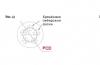
Marburetor solenoid valve control circuit

1 - ignition switch; 2 - generator; 3 - rechargeable battery; 4 - ignition coil; 5 - switch; 6 - control unit; 7 - electromagnetic carburetor valve; 8 - limit switch carburetor.
Engine cooling system fan fan motor

1 - generator; 2 - rechargeable battery; 3 - ignition switch; 4 - the main fuse block; 5 - switching on the electric fan, 6 - electrical fan power sensor; 7 - electric fan; 8 - Additional fuse block
Fuses and relays VAZ 2106

- # 1 Protects the chains of the beep, hours, stop signals, cigarette lighter, lighting lights of open front doors. Nominal fuse 16A.
- №2 Protects the washer chains windshield, wiper (janitors), electric motor VAZ 2106 heater. Nominal fuse 8A.
- №3 Left light lights, as well as a control lamp on the inclusion of dance light in the speedometer (blue). Nominal fuse 8a.
- №4 Protects the right light lights. Nominal fuse 8a.
- №5 Protects from KZ left headlights of near light. Nominal 8a.
- №6 Protects the chain of the right-hand light headlights. Nominal 8a.
- №7 Protects the chain of the trunk lighting lamps, devices, license plate, cigarette lighter, left front lamp of the overall light and the right rear light of the overall light. Nominal 8a.
- No. 8 Protects the chain of the control lamp of the overall light, the license plate lighting lamp, the engine lighting lamp, the right front lamp of the overall light and the left rear light of the overall light. Nominal 8a.
- No. 9 Protects the tachometer chain, winding the rear window heating relay, reverse lamp, discharge lighting, battery charge lamp, turning on the parking brake, brake fluid level, carburetor air damper control, oil pressure pointers, coolant temperature and fuel temperature, turning . Nominal 8a.
- No. 10 protects the battery charging chains, namely the generator excitation chain and the regulator. Nominal 8a.
- №11, 12.13 V basic configuration are in reserve and can be used for additional equipment. The nominal is selected depending on the consumer.
- No. 14 is used to protect the chain of the heating element of the rear window, if so installed. Nominal 16A.
- No. 15 Engine cooling electric fan, if such is installed in the car. Nominal 16A.
- №16 Protects the rotation and alarm indicator circuit. Nominal 8a.
It is important not only to contain contact groups in cleanliness, but also use the fuses of those denominations that the manufacturer recommends. Ignoring these requirements threatens the failure of electrical equipment.
Wiring car VAZ-2105
The supply voltage from the battery to most consumers is supplied through the ignition switch.Regardless of the key position in the ignition switch A sound signal power supply, cigarette lighter, stop signal, interior lighting ceaming, emergency signaling switch, and a portable lamp switching switch remains. All advantages are served on one wire, and the second wire connecting consumers with the power source is the car body. The VAZ-2105 car is the modernization of the VAZ-21011 car.
Electrical Equipment Scheme:
1. Block-headlight. 2. Side rotation indicators. 3. Rechargeable battery. 4. Power on the starter. 5. Pneumoclippace system idle move Carburetor. 6. Sensor top dead Piston points in the first cylinder. 7. Starter. 8. Microswitch carburetor. 9. Headlight cleaners electric motors. 10. Generator. 11. Sound signals. 12. Spark plugs. 13. Podcast lamp. 14. Cooling fluid temperature indicator sensor. 15. Oil pressure control lamp sensor. 16. Spark plug. 17. Windshield washer electric motor. 18. Ignition coil. 19. Sensor of insufficient level of brake fluid. 20. Headlight washer electric motor. 21. Pneumatic valve control unit. 22. Diagnostic shoe. 23. Wiper relay. 24. Relay-breaker of the rotation and alarm indicators. 25. Wiper electric motor. 26. Plug socket for a portable lamp. 27. Stop Signal Switch. 28. VAZ 1405 heater electric motor. 29. Additional resistor of the heater electric motor. 30. Parking brake reference lamp switch. 31. Rear Light Switch. 32. Mounting block VAZ 2105. 33. Relay of inclusion of low headlights. 34. Relay of inclusion of high headlights. 35. Jumper on the location of the sound signals relay. 36. Power on the washer and headlight cleaners. 37. Rear switching on the rear window heating. 38. Lighting lamp discharge box. 39. Cigarette lighter. 40. Plafthrum switches located in door racks. 41. Clamp of internal body lighting. 42. Alarm switcher. 43. The rotation pointer switch. 44. Light headlight switch. 45. Sound Signal Switch. 46. \u200b\u200bSwitch of the washer and windshield wiper. 47. Block of control lamps. 48. Ignition switch. 49. Instrument lighting control switch. 50. Element of heating rear window. 51. The level indicator sensor and fuel reserve. 52 Rear window heating switch with an inclusion control lamp. 53. Switch of the electric motor of the heater. 54. Speedometer. 55. Devices lighting lamp. 56. Far Light Headlight Control Light. 57. Turning indicator lamp. 58. External lighting light. 59. Control lamp of the parking brake. 60. Contact rear fog light switching lamp. 61. Control lamp of the brake fluid level. 62. Voltmeter. 63. Combination of instruments. 64. Rechargeable battery charge lamp. 65. Level pointer and fuel reserve. 66. Oil pressure test lamp. 67. Cooling fluid temperature pointer. 68. Relay interrupter of the parking brake control lamp. 69. Switch outdoor lighting. 70. The fog light switch in the rear lights. 71. Rear lights. 72. Loading lights lighting lights. 73. Ignition relay VAZ 2105.
Implemented wiring diagram VAZ-2114 maximum simple way. Wire function transmitting a negative power supply, performs car body. This scheme is used in most modern cars. There are no complex nodes in the electrical wiring design, each driver can perform independent maintenance and repair. The main thing is to be able to deal with electrical circuits. You do not need to know by heart all the wires and how specifically the node they answer. You must be able to navigate in complex wiring.
Key Features
The main feature of the WAZ-2114 wiring scheme is that it is necessary to feed on all nodes that ensure fuel injection:
- Electronasus fuel.
- Injectors in the fuel ramp.
- System sensors.
Also food is supplied to the electronic control unit and the ignition system. Moreover, only ignition modules were installed, which, in fact, are a switch with built-in coils (all of them two). But on 16-valve engines was put on one coil for each candle. Such a scheme is more perfect, since when the coil fails, only one cylinder will refuse.
In general, the entire car is based on the design of the predecessor - VAZ-2109. The same body shape, used suspension, ignition and fuel feed elements, even the same lanterns are the same. But there are significant differences in the engine design, gearbox. Much more attractive looks new European. It uses more attractive sensors and other devices.
Car wiring design
The total WAZ-2114 wiring scheme can be divided into several components:
- Exterior lighting system.
- Ignition system.
- Fuel feed.
- Engine Management (Sensors, Executive Measures and ECUs).
- Engine launch (starter).
- Power (rechargeable battery and generator).
- Supplementary equipment systems - wipers, washer, stove, heated mirrors, seats and glasses, cigarette lighter, etc.
Absolutely all chains that are connected to the battery are protected by fuses. They are installed in under the hood (as in the predecessor, VAZ-2109).

Switching occurs with the help of electromagnetic relays. They allow you to get rid of the leakage of a large current on the buttons when you turn on powerful consumers. Cause - With direct switching of high currents, the buttons are destroyed and burning contacts. In this regard, electromagnetic relays are much more reliable.
Engine start system
In the wiring diagram of VAZ-2114 (injector and carburetor if in the system), the starter is necessarily present. With it, the engine starts. In this case, the battery is acting as a power source.

The starter consists of such components:
- Stator winding (fixed part).
- Rotary winding (excitation).
- Bendix is \u200b\u200bdesigned for the mechanical connection of the starter rotor and the wint of the flywheel on the crankshaft. Consists of a plug of the drive, overtaking coupling and gears.
- The retractor relay - leads the bendix and power contacts.
- Covers, brush knot and other details.
How does the starter work?
The starter power comes from the battery directly - from the top output of the retractor relay goes to the plus operation of the start system occurs according to such a scheme:
- When turning the ignition key is powered by all components fuel system, ECU.
- When installing the key to the "Start" position, power is supplied to the control output of the traction relay.
- The rotting windings create a magnetic field that makes the core move.
- The power contacts will be closed, and the rotor begins to rotate.
- Bendix simultaneously moves along the rotor axis, and the gear comes into engagement with the crown on the flywheel.
- The crankshaft begins to rotate, the fuel injection in the combustion chamber and the supply of high voltage to the electrodes of the candles.
This is how the entire system of launching the engine of any car, including VAZ-2114, works.
Generator design
The second power source of any car is a generator. It is necessary to power all consumers when the engine is running. The generator consists of the following parts:
- Rotary excitation winding.
- Contact rings on the rotor.
- Bearings.
- Front and back covers.
- Stator winding.
- Voltage regulator.
- Pulley with impeller.
- Diode block.
- Capacitor.

How does the generator work?
When the engine is stopped, the rotary winding is powered. Consequently, there is a magnetic field around it. But since the rotor does not rotate, this field is motionless. Therefore, one of the mandatory conditions of the generator setting is not performed - the magnetic field must be permanent and moving. All conditions are performed only when the starter begins to spin the crankshaft. In this case, the generator generates the voltage supplied to the battery.

But the feature of the design of any automobile generator In the fact that an alternating current is produced. And three phases at the output appear, and for the nutrition of all consumers is needed alternating d.C.. Otherwise, the entire VAZ-2114 subrophto wiring, the diagram of which is presented below, simply burns.

To straighten alternating current, a block of semiconductor silicon diodes is used. The design of the generator with three phases at the output is used for one simple reason - pulsations are much smaller. A condenser is installed on the output of the rectifier - it is possible to get rid of the entire component of the current.
Voltage regulator operation
But there is one huge problem - depending on the speed of rotation crankshaftThe generator can produce a voltage from 10 to 30 volts, and such a scatter is invalid. Therefore, it is necessary to stabilize the voltage at one level - 12 V. In fact, of course, the generators produce a little more - 13.6-14.6 V. only in this case will occur normal charging battery. You can stabilize the outlet voltage, but the problem is that the current consumed is very large.

And Stabilong should have considerable dimensions, respectively, and the cost. But much easier to stabilize the power of the rotor winding. If the magnitude of the voltage supplied to it will be stable, then the magnetic field will not change under any circumstances. This action is carried out using a voltage regulator. The maximum current consumption of the excitation winding is not more than 2 A. Constructively, the regulator is combined with a brush node.
Electronic control unit
Very complex is the wiring scheme of the VAZ-2114 ECU, since it is connected to it a large number of Sensor I.

The electronic control unit is the "brain" of the entire system, it consists of such components:
- Plastic and metal housing.
- The diagram is based on a microcontroller.
- Connecting sensors through a microcontroller
- Signal amplifiers, electronic keys and relays are connected to the outputs of the controller.
The microcontroller allows you to feed signals to actuators, depending on how the engine works. In memory of the ECU laid the algorithm for all systems. Moreover, the wiring diagram of the VAZ-2114 (injector) 8 valves differs from V16, since some more parameters are needed to control the engine.
Control system sensors
On VAZ-2114 cars, several sensors are used, which are connected to electronic block Control. They affect the fuel injection and the moment of ignition.

The system consists of the following sensors:
- Throttle positions.
- The position of the crankshaft.
- Phases (camshaft position).
- Speeds (located on
- Air flow. Instead, the Mar sensor can be used.
- Pressure.
- Detonation.
- Oxygen.
All of these reading devices adjust the fuel mixture supply in the combustion chamber and the ignition advance angle. Wiring diagram VAZ-2114 (injector) with a description is provided in the instruction manual and maintenance of the car. You can also know about how to independently perform troubleshooting, see the document and the main symptoms of the breakdown.
You will also be interested:
The main goal of stating on the body of each car VIN-code is to protect the car from the hijacking. But...
Insufficient or overestimated tire pressure threatens premature failure ...

Drivers who decided to replace the wheels need to accurately calculate the ratio of fasteners ...
Drivers who decided to replace the wheels need to accurately calculate the ratio of fasteners ...
Using automatic selection of tires and discs for the car VAZ 2107, you can avoid ...

