


This diagram shows the most common water cooling scheme for a typical internal combustion engine. The vast majority of modern cars work with such systems.
Cooling system types
Modern engines have two mechanisms and three (or four) systems:
- the mechanism for distributing the flows of the air-fuel mixture and exhaust gases is called the timing;
- crank-connecting rod (KShM) is a mechanism for "coordinating" the movement of the pistons in the cylinders with the operation of the power supply systems and, if provided by the design, the ignition system;
- supply system;
- lubrication system;
- ignition system - only for gasoline (injector and / or carburetor) and gas internal combustion engines, in diesel engines this system is not needed;
- heat removal system, that is, cooling.
In the modern automotive industry, two systems are used - liquid and air. They also call the third - combined, but this, as they say, "in science" - in theoretical mechanics and the theory of the automobile.
At the moment of ignition of the working mixture, the temperature in the cylinders can reach above 2000 ° (two thousand degrees) Celsius, and the cooling system is designed to maintain the calculated temperature balance, which ranges from 90 to 120 degrees. From the point of view of theoretical mechanics, the liquid systems used in modern internal combustion engines are in fact hybrid or combined. However, in practice, and the servicemen themselves, call it liquid, and more often - water, although antifreeze has long been used instead of water.
Liquid cooling systems - specifics
Why water? Why a water-cooled engine? The answer is obvious, it was in automobile engines. Even today, cars of old designs drive on our roads, in which an expansion tank was not even provided. As unnecessary. And the working temperature fluctuated around 70-90 degrees. In modern internal combustion engines, a so-called sealed system is used, and the increased pressure (up to 1.4 atmospheres) allows modern antifreezes not to boil at temperatures up to 120 degrees and - of course - not to freeze down to minus 70-80 degrees Celsius.

The vast majority of liquid cooling systems operate from a centrifugal water pump (pump), as well as under the influence of the natural laws of physics - convection, heating and cooling.
The main components of a liquid cooling system
These systems are single-circuit, double- and multi-circuit. The design of the engine cooling system is not difficult, its "standard list" includes:
- cooling jacket of the cylinder block itself;
- the cooling jacket of the head (or heads) of the cylinder block, both have so-called cooling fins, they are external, which is why the theory of the car calls this system a combined system;
- one or more cooling radiators;
- one or more fans for forced cooling of radiators (or radiator, if there is one);
- a liquid pump, which mechanics call among themselves a water pump or pump; structurally it is a centrifugal pump, drives - gear, belt or electric;
- thermostat (in two-circuit systems of the old type of motors without the use of electronics);
- an expansion tank with a lid not sealed, but calibrated under a certain pressure;
- connecting pipes of the engine cooling system;
- interior heater heat exchanger (or heat exchangers for interior heaters in multi-zone climate control systems);
- coolant temperature sensor (or sensors);
- electronic control unit for cooling, as well as ventilation and heating of the passenger compartment.

In the mechanic's hand is that notorious thermostat that divides the system into two circuits. When the engine warms up, the coolant circulates in a closed, so-called "small circle" without getting into the radiator. Warming up of the cooling jackets of the block and the cylinder head to operating temperatures is faster.
The cooling system of a diesel engine does not fundamentally differ from that of a gasoline engine. The differences are in designs, volumes, capacities and some other parameters, but not in the type of fuel used.
Oil cooling
The lubrication system in modern automobile engines, in addition to its main task - lubrication of rubbing parts, performs another one - heat dissipation: engine oil removes some of the heat from the working mating parts of the engine. Many modern engines even have their own oil cooler, which is called an oil cooler in other technological charts and manuals.
Is air cooling used today?
Yes, it is applied, and quite successfully. In modern motor construction, there are two types of them: natural (by blowing the incoming air) and forced (using fans).
Natural cooling is more commonly used in motor aviation. Forced - for example, in structures such as water and wheel scooters (motor scooters), in motoblocks and other agricultural and communal units and mechanisms.
In the automotive industry, you can recall some models of the Volkswagen Group - Porsche, Beetle, aka Kafer, as well as the Italian Fiat-500, the French Citroën 2CV, the Czech Tatra-613 car, or the native and painfully familiar USSR national car - Zaporozhets.
The history of engine building can also recall air-cooled tractor engines, as well as trucks with multi-cylinder diesel engines. The same, for example, the Czech 12-ton Tatra was produced until 2010 and is still "in service". By the way, the driver's cabin of this dump truck is heated by a special electric heater, and the interior of the Zaporozhets is heated by an autonomous… petrol one.

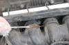
In the photo - "the same" 8-cylinder V-shaped diesel power unit Tatra with direct air cooling. Displacement 12.7 liters with turbocharging and intercooler, power - from 312 to 442 hp, with torque - from 1400 to 2100 Nm, within the framework of compliance with standards from Euro 2 to Euro 5.
Evaporative cooling systems
In the modern automotive industry, it has not found wide application. The mechanics of its work boils down to the fact that the water is brought to a temperature well above the boiling point, and the temperature drops as a result of its evaporation. It was used in experimental models of aircraft construction at the very beginning of the 20th century, and today a similar design can be found on diesel engines with a capacity of up to 20 hp. - on mini tractors, in mobile walk-behind tractors, etc.
Engine cooling system malfunctions
The weakest link in most systems is the radiator. As a rule, they are installed in the front of the car, even if the engine is installed in the base or behind the rear axle. This is done so that the coolant gives off heat to the incoming air stream.
Radiator honeycombs become clogged with fine dust, insects and other road pollution, as a result, the heat conductivity of the radiator drops, and the temperature regime of the engine is disturbed. In addition, radiators are susceptible to mechanical damage at high speeds, which is why, for example, a distinctive feature of a powerful and high-speed machine is a fine mesh in wide and huge air intakes.

Cavitation destruction of a liquid pump of classical design.
The most costly malfunction of an auto mechanic is the breakdown of a water (liquid) pump. As soon as the driver misses the pointer in the red zone of the temperature gauge or the indicator on the instrument panel lit up in red, the consequences can be very sad. Up to engine overhaul.
In motors of old designs, a special headache for car owners was the loss of thermostat functionality.
Also periodically fail:
- sensors and indicators;
- the branch pipe may leak or the clamp on the branch pipe connections may loosen;
- cooling fans do not turn on in time;
- sometimes the pressure valve in the expansion tank plug fails.
These and many other malfunctions lead to the loss of antifreeze, overheating of the block and its head (s) and, ultimately, to the failure of the motor. Any suspicion of a malfunction in the cooling system must be immediately identified and corrected by the driver.
Symptoms of engine overheating or insufficient heating
With critical overheating, the following occurs:
- periodic departure of the arrow of the temperature indicator on the dashboard to the red sector (or the appearance of a red indicator in those cars where the indicator is not provided);
- loss of engine power seemingly "in harmless situations";
- inadequately high heat in the area of \u200b\u200bthe engine compartment.
In case of insufficient heating:
- the arrow “does not come off” from the lower sector of the temperature gauge on the dashboard;
- the yellow (or, in some designs, white) indicator of the temperature gauge does not go out;
- as a result, the engine “dulls”, does not develop the required power - and especially when “when it is needed” - on the rise, when overtaking, during emergency maneuvering and / or acceleration.
These, as well as many others, very specific and obscure to the driver, "inadequacies" in the behavior of the engine, its units and the car as a whole.
Diagnostics of the leakage of the cooling system
One of the main causes of system malfunction is a drop in the level of antifreeze in the expansion tank. In addition to banal drips in leaking joints, the plug on the tank with a calibrated pressure control valve may also fail. The coolant, or rather the water from the ethylene glycol (propylene glycol) solution, simply evaporates, and the coolant level drops, the motor overheats.

It is not difficult to monitor the coolant level in the expansion tank. This is constantly reminded and mentioned: both teachers in driving schools, and various instructions for drivers ... and the engines were boiling and continue to boil. To the delight of mechanics and minders ...
Coolant level control
This level should be monitored constantly. By the way, during operation (during the working day), it can (and should) change in the tank. This is normal. Abnormal - when this level falls below the lower mark, which means a loss of fluid, or - higher, which may mean, for example, a blow-by of crankcase gases into the cooling system. And this is already an extremely disturbing call.
In a specialized service station, the level and pressure in the system is monitored using special equipment and tools. An ordinary car owner has only one technique in his arsenal - a systematic visual control of the level in the upper radiator tank (on cars of old designs, without an expansion tank) or - in an expansion tank for special risks - max and min.
If you miss it, it's a problem!
If you have any questions - leave them in the comments below the article. We or our visitors will be happy to answer them
Briefly about how the car engine cooling system works.
Answer the question which part of the car is more important:, or the engine cooling system? If you selected one or two of the suggested positions in the list, you answered incorrectly. In fact, all of the above positions are vital for any car. Failure in each of them will lead to serious consequences, which will not be easy to fix.

Take, for example, a motor cooling system. If it is faulty or the engine operating mode exceeds the performance indicators laid down in its design, there is a possibility that you can see a rare phenomenon that will later come to you in nightmares, thick hot steam will begin to pour from under the hood, and the arrow of the engine temperature sensor will rest against the red zone indicates critical overheating of the motor. After such a steam bath and extreme temperatures, the engine may well go to a car service for overhaul or straight to a landfill. This is the result of a malfunctioning cooling system.
And so, the first useful information for beginners. The purpose of the cooling system is to create ideal thermal conditions for the engine, which will eliminate the possibility of overheating. Exothermic reactions occur in the internal combustion engine (that is, it produces a large amount of heat) and if the cooling system is not able to take away excess heat from the cylinder block, the engine will begin to deform (it can drive the cylinder head), the oil will not be able to provide sufficient protection (its protective properties deteriorate), the engine will begin to wear out quickly and will eventually jam.
The most important part of the engine cooling system is by far the water pump. It forces ethylene glycol-based coolant to circulate through the hottest parts of the engine, as well as through the thermostat housing, radiator, heater radiator, and other pipes and hoses that go into the cooling system.
All internal combustion engines are cooled by convective heat transfer (heat transfer in unevenly heated liquid, gaseous and other fluids, read more here: yandex.ru) and almost all modern cars use a liquid based on ethylene glycol as liquid antifreeze. It has a number of advantages over other technical fluids, such as high heat capacity, very high boiling point and low freezing point. It is it that is pumped through the engine by a water pump driven from the crankshaft by a drive belt for the drive of auxiliary units.

How does the thermostat work?
The thermostat uses wax. Wax poured into a brass or aluminum capsule, when heated, pushes a small piston away from the thermostat housing, compressing the spring. The thermostat opens. After cooling the system, the spring returns the thermostat to the closed position (the thermostat operation is shown in the 5.37 minute of the video. By the way, this option shown can be used as a check of the thermostat operation from your car, if you doubt its correct functioning)
On a cold engine, the coolant flows in a so-called small circle through the cylinder block, the cylinder head called the "head" and (for this reason, you immediately get warm air in the cabin after starting the engine).
Once the engine reaches about 95 degrees, the wax in the thermostat expands and opens the valve, directing coolant from the engine to the radiator.
How does the cooling radiator work?

The heated coolant passes through the radiator tubes, giving off heat from the coolant (liquid) to the tubes, then transferring it to the radiator fins (the fins are made of corrugated metal). The fins, with their large surface area, contribute to high heat transfer when meeting the incoming flow of cooled air (to increase the cooling effect or in cases where the car is stationary, a large fan is placed in front of the radiator, which additionally drives air through the cooling fins). Thus, the coolant flowing through the radiator grill is cooled and enters the opposite tank on the radiator. The cycle repeats, the cooled liquid returns to the water pump and cools the engine, the circle is closed.

A cut of the radiator shows us two rows of tubes through which coolant flows, which transfers heat from the engine to the grille fins.
When fuel is burned inside the cylinder, the gas temperature rises to 2000 ° C. Heat is spent on mechanical work, partly carried away with exhaust gases, spent on radiation and heating of engine parts. If it is not cooled, then it loses power (the filling of the cylinders with the working mixture worsens, premature self-ignition of the mixture occurs, etc.), the wear of parts increases (oil burns out in the gaps) and the probability of their breakdown as a result of a decrease in the mechanical properties of materials increases.
If the engine is supercooled, the amount of heat transferred to work decreases, the fuel condenses on the cold cylinder walls, flows into the crankcase (oil reservoir) and dilutes the lubricant, which also leads to increased wear of rubbing parts and a decrease in engine power. Thus, maintaining a certain thermal condition of the engine is important and imperative. Therefore, all car engines have a cooling system.
There are liquid and air cooling systems. Liquid cooling systems have become more widespread, since with their help a more favorable thermal regime is created for engine parts, the possibility of manufacturing engine parts from relatively inexpensive materials. Such engines create less noise during operation due to the presence of double walls (jacket) and a layer of coolant.
1 - heater radiator |
21 - the right radiator tank |
|---|
Cooling system - liquid, closed type, with forced circulation. The tightness of the system is ensured by the inlet and outlet valves in the expansion tank plug. The exhaust valve maintains an increased (compared to atmospheric) pressure in the system on a hot engine (due to this, the boiling point of the liquid becomes higher, and steam losses are reduced). It opens at a pressure of 1.1-1.5 kgf / cm2. The inlet valve opens when the pressure in the system decreases relative to atmospheric pressure by 0.03-0.13 kgf / cm2 (on a cooling engine).
The thermal mode of the engine is maintained by a thermostat and an electric radiator fan. The latter is turned on by a sensor screwed into the left radiator tank (on a VAZ-2110 engine) or through a relay on a signal from an electronic engine control unit (on VAZ-2111, -2112 engines). The sensor contacts close at a temperature of 99 ± 2 ° С, and open at a temperature of 94 ± 2 ° С.
To monitor the temperature of the coolant, a sensor connected to the temperature gauge on the dashboard is screwed into the cylinder head of the engine. An additional temperature sensor is installed in the outlet pipe of injection engines (VAZ-2111, -2112), which provides information for the electronic engine control unit.
The coolant pump is a vane, centrifugal type, driven from the crankshaft pulley by a toothed timing belt. The pump body is aluminum. The roller rotates in a double-row bearing with a "lifetime" supply of grease. The outer bearing ring is secured with a screw. A toothed pulley is pressed onto the front end of the roller, and an impeller is pressed onto the rear end. A thrust ring made of a graphite-containing composition is pressed against the impeller end, under which there is an oil seal. If the pump fails, it is recommended to replace the complete pump.
The redistribution of fluid flows is controlled by a thermostat. On a cold engine, the thermostat bypass valve closes the pipe leading to the radiator, and the fluid circulates only in a small circle (through the thermostat bypass pipe), bypassing the radiator. On a VAZ-2110 engine, a small circle includes a heater radiator, an intake manifold, a carburetor heating unit and a liquid chamber of a semi-automatic starting device. On VAZ-2111, -2112 engines, the liquid, in addition to the heater, is supplied to the throttle unit heating unit (heating of the intake manifold is not provided).
At a temperature of 87 ± 2 ° C, the bypass valve of the thermostat begins to move, opening the main branch pipe; while part of the liquid circulates in a large circle through the radiator. At a temperature of about 102 ° C, the pipe opens completely, and all the liquid circulates in a large circle. The main valve travel must be at least 8 mm.
The thermostat of the VAZ-2112 engine has an increased resistance of the bypass valve (throttle hole), due to which the flow of fluid through the heater radiator increases.
Coolant is poured into the system through the expansion tank. It is made of translucent polyethylene, which allows you to visually monitor the liquid level. The on-board monitoring system also reports a drop in the liquid level; for this, a sensor is provided in the tank lid. Two vapor pipes are also connected to the reservoir: one from the heater radiator, the other from the engine cooling radiator.
The radiator consists of two vertical plastic tanks (left - with a partition) and two horizontal rows of round aluminum tubes with pressed-on cooling plates. To improve the cooling efficiency, the plates are stamped with a notch. The tubes are connected to the tanks through a rubber gasket. The liquid is supplied through the upper branch pipe and discharged through the lower one. Next to the inlet is a thin tube for the steam pipe.
The capacity of the liquid cooling system depends on the size and degree of boost (for example, compression ratio) of the engine and averages 0.2, 0.3 liters per horsepower. Therefore, in cars, it contains up to 8 ... 12 liters of liquid, in trucks with a gasoline carburetor engine - up to 30 liters, and in trucks with a diesel engine - up to 50 liters. Antifreeze containing anti-corrosion and anti-foaming additives, as well as additives that exclude the formation of scale, grade A-40 or A-65 antifreeze has a thickening temperature of 40 and -65 ° C, respectively. When the engine is running, the fluid that washes its cylinders and head heats up and opens an automatic valve (thermostat) located in the pipeline connecting the engine to the radiator. A pump, driven by the crankshaft, circulates fluid in the system. Hot liquid, passing through the radiator tubes, gives off heat to the air supplied to it by the fan. The engine cooling rate can be changed by changing the rate of fluid circulation or the rate of air flow through the radiator, depending on the ambient air temperature or driving conditions (speed, load, etc.).
The cooling system of an internal combustion engine is designed to remove excess heat from engine parts and assemblies. In fact, this system is bad for your pocket. Approximately one third of the heat obtained from the combustion of the precious fuel has to be dissipated in the environment. But such is the structure of a modern ICE. The ideal would be an engine that can work without dissipating heat into the environment, and turn all of it into useful work. But the materials used in modern engine building will not withstand such temperatures. Therefore, at least two basic, basic engine parts - the cylinder block and the block head - have to be additionally cooled. At the dawn of the automotive industry, two cooling systems appeared and competed for a long time: liquid and air. But the air cooling system gradually lost ground and is now used mainly on very small motor vehicles and low-power generator sets. Therefore, let's take a closer look at the liquid cooling system.
Cooling system device
The cooling system of a modern automobile engine includes an engine cooling jacket, a coolant pump, a thermostat, connecting hoses and a radiator with a fan. The heater heat exchanger is connected to the cooling system. Some engines also use coolant to heat the throttle assembly. Also, in engines with a supercharging system, there is a supply of coolant to the liquid-air intercoolers or to the turbocharger itself to reduce its temperature.
The cooling system works quite simply. After starting a cold engine, the coolant begins to circulate in a small circle with the help of a pump. It passes through the cooling jacket of the block and cylinder head of the engine and returns to the pump through the bypass (bypass) pipes. In parallel (on the vast majority of modern cars), the liquid is constantly circulating through the heater heat exchanger. As soon as the temperature reaches the set value, usually around 80–90 ° C, the thermostat starts to open. Its main valve directs the flow to the radiator, where the liquid is cooled by the counterflow of air. If the air blowing is not enough, then the cooling system fan comes into operation, in most cases having an electric drive. The movement of fluid in all other components of the cooling system continues. The bypass channel is often an exception, but it does not close on all vehicles.
In recent years, cooling systems have become very similar to one another. But two fundamental differences remain. The first is the location of the thermostat before and after the radiator (in the direction of fluid flow). The second difference is the use of a pressurized circulating expansion tank, or an unpressurized tank, which is a simple reserve volume.
Using the example of three schemes of cooling systems, we will show the difference between these options.
Components
Cylinder head and block jacket are channels cast in an aluminum or cast iron product. The channels are sealed, and the joint between the block and the cylinder head is sealed with a gasket.
Coolant pump blade, centrifugal type. It is driven in rotation either by the timing belt or by the accessory drive belt.
Thermostatis an automatic valve that is triggered when a certain temperature is reached. It opens, and part of the hot liquid is discharged into the radiator, where it cools down. Recently, electronic control of this simple device has begun to be applied. They began to heat the coolant with a special heating element to open the thermostat earlier if necessary.
Fluid change and flushing
If you did not have to replace any unit in the cooling system earlier, then the instructions recommend changing the antifreeze at least every 5-10 years. If you did not have to add water to the system from a canister, and even worse - from a roadside ditch, then when changing the fluid, the system does not need to be flushed.
But if the car has seen a lot in its lifetime, then it is useful to make it when changing the fluid. Having opened the system in several places, you can thoroughly rinse it with a stream of water from a hose. Or, simply drain the old liquid and pour clean, boiled water. Start the engine and warm up to operating temperature. After waiting for the system to cool down, so as not to burn yourself, drain the water. Then purge the system with air and add fresh antifreeze.
Flushing of the cooling system is usually started in two cases: when the engine overheats (this is manifested primarily in the summer period) and when the stove stops heating in winter. In the first case, the reason lies in the radiator pipes overgrown with dirt on the outside and clogged from the inside. In the second, the problem is that the heater radiator tubes are clogged with deposits. Therefore, during a planned fluid change and when replacing components of the cooling system, do not miss the opportunity to thoroughly flush all the components.
The illustration shows the liquid cooling system of a carbureted V-engine. Each row of the block has a separate water jacket. The water injected by the water pump 5 is divided into two streams - into the distribution channels and then into the water jacket of its block row, and from them into the cylinder head jackets.
Figure: Cooling system of the ZMZ-53 engine: a - device; b - core; c - blinds; 1 - radiator; 2 - liquid overheat indicator sensor; 3 - radiator plug; 4 - casing; 5 - water pump; 6 - bypass hose; 7 and 12 - outlet and supply hoses, respectively; 8 - thermostat; 9 - liquid temperature sensor; 10 - fitting of the drain cock; 11 - cooling jacket; 13 - fan belt; 14 - drain cock; 15 - fan; 16 - blinds; 17 - heater fan; 18 - cab heater; 19 - louver plate; 20 - cable
During the operation of the cooling system, a significant amount of liquid is supplied to the most heated places - the exhaust valve pipes and the sockets of spark plugs. In carburetor engines, water from the cylinder head jackets preliminarily passes through the water jacket of the intake pipe, washes the walls and heats the mixture coming from the carburetor through the internal channels of the pipe. This improves the evaporation of gasoline.
The radiator is used to cool the water coming from the engine water jacket. The radiator consists of upper and lower tanks, a core and mounting parts. The tanks and core are made of brass for better heat conduction.
The core contains a series of thin plates through which a plurality of vertical tubes pass, soldered to them. Water entering through the radiator core splits into a large number of small streams. With this structure of the core, the water is cooled more intensively due to the increase in the area of \u200b\u200bcontact of the water with the walls of the tubes.
The upper and lower tanks are connected with hoses 7 and 12 to the engine cooling jacket. A tap 14 is provided in the lower tank for draining water from the radiator. To drain it from the water jacket, there are also taps (on both sides) at the bottom of the cylinder block.
Water is poured into the cooling system through the neck of the upper tank, closed with a plug 3.
The hot water is supplied to the cabin heater 18 from the water jacket of the block head and is discharged by a pipe to the water pump. The amount of water supplied to the heater (or the temperature in the driver's cabin) is controlled by a tap.
The liquid cooling system provides for double regulation of the thermal regime of the engine - with the help of louvers 16 and thermostat 8. The louvers consist of a set of plates 19, which are hinged in the bar. In turn, the bar is connected to the shutter control handle by a rod and a system of levers. The handle is located in the cab. The leaves can be arranged vertically or horizontally.
The water pump and fan are combined in one housing, which is attached to the platform on the front wall of the crankcase through a gasket. A roller 4 is installed in the pump housing 7 on ball bearings. At its front end, a pulley 2 is fixed by means of a hub. A cross is screwed to its end, to which the fan impeller 1 is riveted. When the engine is running, the pulley receives rotation from the crankshaft through the belt. The impeller blades 1, located at an angle to the plane of rotation, take air from the radiator, creating a vacuum inside the fan casing. This allows cold air to pass through the core of the radiator, taking away heat from it.
At the rear end of the roller 4, the impeller 5 of a centrifugal water pump is rigidly mounted, which is a disk with curved blades evenly spaced on it. When the impeller rotates, the liquid from the inlet pipe 8 flows to its center, is captured by the blades and, under the action of centrifugal force, is thrown to the walls of the housing 7 and is fed through the tide into the water jacket of the engine.

Figure: Water pump and fan of the ZIL-508 engine: 1 - fan impeller; 2 - pulley; 3 - bearing; 4 - roller; 5 - pump impeller; 6 - gasket; 7 - pump body; 8 - inlet pipe; 9 - bearing housing; 10 - cuff; 11 - sealing washer; 12 - a cage of the stuffing box seal
At the rear end of the shaft 4, a stuffing box seal is also provided, which does not allow water to pass from the water jacket of the engine. The seal is mounted in a cylindrical impeller hub and is locked in it with a spring ring. It consists of a textolite sealing washer 11, a rubber cuff 10 and a spring that presses the washer to the end of the bearing housing. With its projections, the washer enters the grooves of the impeller 5 and is secured by the holder 12.
On the engine of a KamAZ car, the fan is located separately from the water pump and is driven through a hydraulic clutch. The fluid coupling (Fig. A) includes a hermetic casing B filled with liquid. The casing contains two (with transverse blades) spherical vessels D and D, rigidly connected to the driving A and driven B shafts, respectively.
The principle of operation of the fluid coupling is based on the action of the centrifugal force of the fluid. If you quickly rotate a spherical vessel D (pumping) filled with a working fluid, then under the action of centrifugal force, the liquid slides along the curved surface of this vessel and enters the second vessel G (turbine), forcing it to rotate. Having lost energy on impact, the liquid again enters the first vessel, accelerates in it, and the process is repeated. Thus, rotation is transferred from the drive shaft A, connected to one vessel D, to the driven shaft B, rigidly connected to another vessel D. This principle of hydrodynamic transmission is used in technology when designing various mechanisms.

Figure: Hydraulic coupling: a - principle of operation; b - device; 1 - cylinder block cover; 2 - case; 3 - casing; 4 - drive roller: 5 - pulley; 6 - fan steps; A - leading shaft; B - driven shaft; B - casing; D, D - vessels; T - turbine wheel; H - pump wheel
The fluid coupling is located in the cavity formed by the front cover 1 of the cylinder block and the housing 2, connected by screws. The fluid coupling consists of a casing 3, pumping H and turbine G wheels, driving A and driven B shafts. The casing is connected through the drive shaft A to the crankshaft using the drive shaft 4. On the other hand, the casing 3 is connected to the pump wheel and the pulley 5 of the generator and water pump drive. The driven shaft B rests on two ball bearings and is connected at one end to the turbine wheel, and the other to the fan hub 6.
The engine fan is located coaxially with the crankshaft, the front end of which is connected by a splined shaft to the drive shaft 4 of the fluid coupling drive. By turning the lever of the hydraulic clutch switch, one of the required operating modes of the fan can be set: "P" - the fan is constantly on, "A" - the fan turns on automatically, "O" - the fan is off (the working fluid is drained from the casing). Only short-term work is allowed in the "P" mode.
The fan automatically turns on when the temperature of the coolant that washes the thermo-force sensor rises. At a coolant temperature of 85 ° C, the sensor valve opens the oil channel in the switch housing and the working fluid - engine oil - enters the working cavity of the fluid coupling from the main line of the engine lubrication system.
The thermostat serves to accelerate the warm-up of a cold engine and automatically regulate its thermal regime within the specified limits. It is a valve that regulates the amount of circulating fluid through the radiator.
On the engines under study, single-valve thermostats with a solid filler - ceresin (petroleum wax) are used. The thermostat consists of a housing 2, inside which is placed a copper balloon 9 filled with an active mass 8, consisting of copper powder mixed with ceresin. The mass in the cylinder is tightly closed by a rubber membrane 7, on which a guide sleeve 6 with a hole for a rubber buffer 12 is installed. The latter has a stem 5 connected by a lever 4 to the valve. In the initial position (on a cold engine), the valve is tightly pressed against the seat (Fig. B) of body 2 by a spiral spring 1. The thermostat is installed between the pipes 10 and 11, which drain the heated liquid into the upper radiator tank and the water pump.

Figure: Thermostat with rotary (a-c) and simple (d) valves: a - device of a thermostat with a rotary valve (ZIL-508 carburetor engine); b - the valve is closed; в - the valve is open; d - thermostat device with a simple valve (3M3-53 carburetor engine); 1 - spiral spring; 2 - case; 3 - valve (damper); 4 - lever; 5 - stock; 6 - guide sleeve; 7 - membrane; 8 - active mass; 9 - balloon; 10 and 11 - branch pipes for drainage of liquid into the radiator and water pump; 12 - rubber buffer; 13 - valve; 14 - spring; 15 - body saddle; A - valve stroke
At a coolant temperature above 75 ° C, the active mass will melt and expand, acting through the membrane, buffer and rod 5 on lever 4, which, overcoming the force of spring 1, begins to open valve 3 (Fig. C). The valve will open completely at a coolant temperature of 90 ° C. In the temperature range 75 ... 90 ° C, the thermostat valve, by changing its position, regulates the amount of coolant passing through the radiator, and thereby maintains the normal temperature of the engine.
Figure d shows a thermostat with a simple valve 13 in the position when it is fully open for the passage of liquid into the radiator, i.e. when its stroke is equal to distance A. At a temperature of 90 ° C, when the active mass of the cylinder is melted, the valve together with the cylinder sits down, overcoming the resistance of the spring 14. As it cools, the mass in the cylinder is compressed and the spring lifts the valve up. At a temperature of 75 ° C, valve 13 is pressed against the seat 15 of the body, closing the liquid outlet to the radiator.

Figure: Air-steam valve: a - the steam valve is open; b - air valve is open; 1 and 6 - steam and air valves, respectively; 2 and 5 - steam and air valve springs; 3 - steam outlet pipe; 4 - plug (cover) of the radiator filler neck
A steam-air valve is required to communicate the interior of the radiator with the atmosphere. It is mounted in the radiator filler cap 4. The valve consists of a steam valve 1 and an air valve 6 located inside it. The steam valve, under the action of a spring 2, tightly closes the radiator neck. If the temperature of the water in the radiator rises to the limit value (for a given engine), then under the steam pressure, the steam valve opens and its excess flows out.
When a vacuum is created in the radiator during water cooling and steam condensation, the air valve opens and atmospheric air enters the radiator. The air valve closes under the action of spring 5 when the air pressure inside the radiator is equal to atmospheric pressure. The air valve is used to drain water from the cooling system when the filler cap is closed. In this case, the radiator tubes are protected from destruction under the influence of atmospheric pressure during the cooling of the engine.
A warning light and a remote thermometer are used to monitor the coolant temperature. The lamp and thermometer are located on the instrument panel, and their sensors can be in the cylinder head, in the riser pipe, in the intake manifold, or in the upper radiator tank.
You will also be interested in:
The Korean car "Hyundai Solaris" belongs to the category of inexpensive sedans that ...

Car owners often have questions: "What size wheels fit on a car?" and...

It just so happened that in most cases only a convertible could afford ...

Today there are many brands of cars, each of which has its own ...

Mercedes-Benz is one of the largest and best car manufacturers today ...

