


Adjustment of the UAZ Patriot bridge is quite debts and a laborious process, which includes many nuances that must be consistently performed in order to avoid problems during repairs.
Bridge adjustment is needed if problems arise in the form of broken teeth, oil leakage, bearing wear, etc. This is possible not because the quality of the parts leaves much to be desired, but because of improper operation of the car, as well as if the clearance in the bearings is incorrectly set pinion of the main drive, lack of oil or its poor quality. The consequences of this can be as extraneous noise in the bridge, fuel consumption, deterioration in handling, increased wear of parts and you can even catch a wedge of the bridge.
Whatever this happens, it is necessary to carry out special repair work in a timely manner, such as replacing oil seals, replacing and adjusting bearings. At the end of such work, you should check the correctness of the axle adjustment, you can determine the temperature of the axle after a fast ride.
Remember that a timely oil change will prolong the life of your parts!
If you have a problem with fuel consumption, this will help you
 - Breakage of the teeth of the main pair.
- Breakage of the semi-axle teeth.
- Oil leaking through oil seals.
- Wear or destruction of differential bearings.
- Wear or destruction of the teeth of the main pair.
- Wear and destruction of hub bearings.
- Destruction of the adjusting washers.
Causes of malfunctions
- Incorrect operation. UAZ Patriot is rear wheel drive
car with plug-in  front axle. If you drive with the front axle connected on hard roads, and even with turns (!), Then the transmission will not last long.
- The presence of an axial clearance in the bearings of the main drive pinion.
- The presence of axial play in the bearings of the differential of the main drive.
- Wear of parts, usually due to a lack of the required quantity and quality of gear oil.
- Wear of parts due to poor quality. Quality bearings, adjusting rings should be looked for.
- Overloading during operation due to necessity (for example, competition) or inability to drive.
- Incorrect adjustment of the main pair.
- Not timely replacement of transmission oil.
- Operation with a transmission oil brand out of season.
- Overloads from interlocks.
- Long-term operation with different tire pressures.
- Propeller shaft runout (poor shaft quality, destruction of the crosspieces, destruction of the outboard bearing).
- Lack of grease in the splined joint of the propeller shaft.
- Incorrect tuning - the length and travel of the propeller shaft do not correspond to the changes made.
- Incorrect tuning - incorrect transmission ratios.
- Lack of high-quality lubrication in the bearing hubs.
- Prolonged slipping of one wheel while fixing the other wheel.
- Incorrect and untimely adjustment of the hub bearings.
Consequences of malfunctions - Rear and front axle UAZ Patriot
- Noise in the bridge.
- Increased fuel consumption.
- Deterioration of handling.
- Increased wear of transmission and engine elements due to increased load.
- Jamming while driving is the worst. The main reason for axle jamming is the presence of axial clearance in the bearings of the main gear drive gear or the presence of axial clearance in the bearings of the main gear differential. The jamming of the rear axle of the UAZ Patriot really happens if the owner has completely started his car or is treating him completely disgracefully, since before the bridges become jammed, they are told with a prolonged hum, noise and crackling that they need repairs. Bridge can jam if it gets very hot
Rear and front axle
Cause of malfunction and remedy
Continuous increased noise during front axle operation
1. Worn or incorrectly adjusted differential bearings.
2. Incorrect adjustment. damage or wear of gears or gearbox bearings.
3. Insufficient amount of oil in the axle housing.
1.1 Replace worn parts, adjust differential bearing.
2.2. Determine if the gearbox is faulty, repair or replace it
3.3. Restore the oil level, check if there is no oil leakage through the seals of the front axle housing
Noise during vehicle acceleration and engine braking
1. Incorrect adjustment of the meshing of the main gears.
2. Incorrect lateral clearance in the meshing of the final drive gears.
3.Increased clearance in the pinion bearings due to a loose flange nut or bearing wear. 1.1. Adjust the engagement.
2.2 Adjust the clearance.
3.3 Adjust the clearance, replace the bearings if necessary.
Knock at the start of the vehicle
Worn hole for the pinion shaft in the differential box Replace the differential box and, if necessary, the pinion pin
Replacing the oil seal of the drive gear shaft of the front axle reducer
Replace the oil seal if oil leaks from under the gearbox flange.
Front axle final drive bearing adjustment
Adjust the final drive bearings in the following order.
1. Select the adjusting ring 5 (see Fig. 6.4). Its thickness d1 (Fig. 6.5) is determined (with an accuracy of + -0.025 mm) based on the actual dimensions B and D (see Fig. 6.5 and 6.6) by the formula d1 \u003d B - (111.960 + D) (mm).
Figure: 6.6. Differential bearing adjustment parameters
Figure: 6.7. Measuring the mounting height of the main drive pinion bearing:
1 - mandrel; 2 - outer bearing race; 3 - bearing
Install the ring in the crankcase 16 (see Fig. 6.4) of the main gear.
2. Install the pinion shaft into the front axle housing.
Note
Check the torque of the pinion shaft. It should be 1.0-2.0 N / cm (0.1-0.2 kgf / cm).
3. When installing the differential assembly with the driven gear, measure dimension E (Fig. 6.7), applying an axial force P equal to 4000-5000 N (400-500 kgf), and turning the gear several times so that the bearing rollers take the correct position. Measure the distance B in the crankcase (see Fig. 6.5) from the pinion axle to the thrust end of the differential bearing. For the actual dimensions B, E and the mounting size of the driven gear equal to 50 mm, select (with an accuracy of + -0.025 mm) the adjusting ring according to the formula
d2 \u003d B - (E + 50 + X) (mm), where d2 is the thickness of the adjusting ring;
X is the maximum deviation from the mounting dimension, equal to 50 mm, with a corresponding sign (plus or minus), this dimension is electrograph applied to the end face of the driven gear.
4. Install the differential assembly with the outer rings of its bearings and the adjusting ring in the front axle housing and secure it.
5. Adjust bearings 6 and 22 (see Fig. 6.4) of the front axle differential by tightening nut 23, periodically rotating the differential so that the bearing rollers take the correct position. After tightening the nut, the total turning torque of the differential drive gear (Mv.sh.) Should be within Mw. sh. + (0.21-0.42) (Nm). Check by turning by the pinion gear.
Fig. (6.8.) Measuring the installation dimension of differential with bearing:
1, 5 - mandrel; 2 - differential assembly with a driven gear; 3 - bearing; 4 - outer bearing race
Note
Check and adjust the lateral clearance in the meshing of the gear wheels of the installed new final drive set after adjusting the position of the gears.
The lateral clearance is checked with an indicator, the stand of which is attached to the bridge housing in a direction perpendicular to the tooth surface of the driven gear when attached to the housing of the indicator stand. Check the clearance on three to four teeth, evenly spaced around the circumference. The spread of clearance values \u200b\u200bshould not exceed 0.05 mm. Normal side clearance should be between 0.15 and 0.25 mm. If the side clearance is less than the specified value, then the selected adjusting ring should be replaced with a ring of a smaller thickness. It is not necessary to preload the differential bearings when checking and adjusting the lateral clearance.
6. Tighten the adjusting nut 23 until it comes into contact with the bearings and there is no clearance in them.
7. Check the meshing of the main gears by the contact patch, for which paint the teeth of the driven gear with paint (2 teeth in three or four places evenly around the circumference). 8. While braking the drive gear shaft by the flange, rotate the driven gear in both directions until contact spots appear on the gear teeth, as shown in fig. 6.8.
Note
With correct adjustment of the gear engagement, the contact patch should be located in the places of the teeth shown in Fig. 6.8 (item 1).
In case of contact at the top of the tooth (key 2), move the drive gear to the driven gear, increasing the thickness of the adjusting ring, and to maintain the value of the side clearance, move the driven gear away from the driving gear.
In case of contact at the base of the tooth (key 3), move the drive gear away from the driven gear, reducing the thickness of the adjusting ring, and to maintain the value of the lateral clearance, move the driven gear to the drive gear.
Figure: (6.9.) The location of the contact patch on the teeth of the main gears:
A - forward side; B - reverse side; 1 - correct location; 2 - the contact patch is located at the apex of the tooth; 3 - the contact patch is located at the base of the tooth; 4 - the contact patch is located at the narrow end of the tooth; 5 - the contact patch is located at the wide end of the tooth
In case of contact at the narrow end of the tooth (key 4), move the driven gear away from the driving gear, reducing the thickness of the adjusting ring, while moving the driving gear to the driven gear to maintain the value of the side clearance.
In case of contact at the wide end of the tooth (key 5), move the driven gear to the drive gear, increasing the thickness of the adjusting ring, and to maintain the value of the lateral clearance, move the drive gear away from the driven gear.
9. Install the locking plate onto the differential bearing cover.
10. After assembling the final drive, check its heating after making a test drive on the car. If the front axle housing in the area of \u200b\u200bthe pinion bearings and differential bearings heats up over 90 ° C, then re-adjust the preload
Elimination of leakage through axle hubs
It will take: new cover bolts (optional), thread locking lubricant, sealant, degreaser (white spirit or kerosene).
- Jack up the wheel or lift the car on a lift.
- Remove the hub cover.
- The bolts must be thoroughly cleaned in a solvent and dried.
- Clean the cap and hub in solvent and dry.
- Clean the threads in the hub with solvent and dry.
- Move the cover up to the hub and check that it is tight and not distorted.
- Apply (smear) a thin even layer of sealant to the cap and hub.
- Align the bolt holes in the cover and the hub.
- Apply lubricant to the threads of the bolts to secure the threaded connections, tighten the bolts (without washers).
- Tighten bolts evenly and finally tighten.
- The sealant should creep out evenly around the edges. After it hardens, cut off the excess.
- Do not lower the car on wheels for at least one hour until the sealant hardens.
Filler plug and drain plug
The filler plug of the gearbox tends to sour tightly over time. This is due to the fact that the thread in it is tapered.
Without waiting for this moment, you should unscrew it, clean (wipe) the plug and thread on the gearbox with a degreasing agent (white spirit or kerosene).
Lubricate the thread of the plug with a high-quality grease to fix the threaded connections without regretting the amount of grease.
Tighten the plug to such an extent that there is no oil leakage without overtightening.
Replacement of oil seals of the UAZ Patriot bridge
How to replace the rear axle oil seal.
Replacing the axle gearbox oil seal on the UAZ Patriot:
Correctly installed, high-quality oil seals last a very long time.
Never reinstall used removed oil seals.
Purchase quality oil seals.
If high-quality oil seals quickly begin to leak, then the reason should not be sought in the oil seals, but in the adjustment of the bridge, the fastening and quality of the propeller shaft, crosses, and outboard bearing.
- Unscrew the propeller shaft.
- Unscrew the flange fixing nut (nut of the drive pinion shaft of the rear axle reducer).
- Remove the flange.
- Remove the oil seal from the throat of the gearbox with a flat screwdriver.
- Clean the place where the oil seal is installed with a degreaser (white spirit or kerosene).
- Before installation, lubricate the inside of the oil seal, the one that should come into contact with the shaft and oil, with gear oil.
- When installing, an old oil seal is sometimes used as a pressure test. It is advisable to flush such an oil seal, so as not to "infect".
- The process of installing the oil seal in place must be accurate, without distortion, both as a result of installation and in the process of pressing.
- After installation, the inner (working) part of the oil seal, i.e. the places of friction, lubricate again with the fluid in which it will work - transmission oil.
- Install the parts upside-down. When installing the flange, while tightening the nut, turn it by the flange so that the bearing rollers are in place.

1 - bolt; 2, 33 - spring washers; 3 - driven gear; 4, 24 - semi-axes; 5 - an adjusting ring; 6, 22 - bearings; 7 - spacer sleeve; 8 - outer cage of the outer roller bearing; 9 - roller bearing; 10 - thrust ring; 11 - oil seal; 12 - reflector; 13- flange; 14 - washer; 15 - nut; 16 - bridge housing; 17 - an adjusting ring of the driving gear; 18 - outer cage of the inner roller bearing; 19 - inner roller bearing; 20 - oil deflector ring; 21 - shaft with a driving gear; 23 - differential bearing adjusting nut; 25, 39 - right and left parts of the differential housing; 26 - bolt; 27, 40 - support washers of the semi-axle gears; 28, 43 - semi-axle gears; 29, 45 - axles of differential satellites; 30, 41, 44, 46 - differential satellites; 31, 38 - differential bearing caps; 32 - retainer for differential bearing adjusting nut; 34, 36, 37 - bolts; 35 - cover of the main gear housing; 42 - gasket for the cover of the final drive housing
UAZ Patriot bridge is regulated selection of adjusting rings and tightening the differential and final drive bearings.
The selection of the adjusting rings ensures the correct meshing of the main gears. The correct meshing of the main gears is checked by the contact patch.
The correct tightening of the bearings is determined by the total torque, the value of which is measured in Nm. Naturally, in practice, no one is interested in these units. The process of tightening bearings is solely determined by the skill and experience of the craftsman. To check the correctness of the bridge setting, special measuring devices are used.
After repair and adjustment of the UAZ Patriot bridge, it should not "hum" from the very beginning of operation. If in the first days of operation the bridge hums, then after running in the hum will not disappear. During break-in, a serviceable and correctly adjusted axle does not buzz. Without proper repair, "humming" bridges will not hum less.
 To check the correct adjustment of the UAZ Patriot bridge, it is not at all necessary to be able to adjust it. Before doing anything, check the axle temperature after driving fast. If the bridge gets very hot, then you can definitely say that it, at least, needs to be regulated. If such a bridge is not repaired, sooner or later it will jam.
1. Unscrew the universal joint from the bridge. On a raised car, rotating the axle flange (the universal joint) by hand in both directions, you can feel the presence of broken teeth, assess the condition of the bearings and other problems.
2. After removing the axle cover, check the condition of the teeth on the main gear and differential by turning the axle. There should be no cracks, workings, roughness in the places of contact spots, cuts and torn off teeth. Assess the location of the contact patch. In the crankcase, you can sometimes find the remains of destroyed shims and broken elements. These problems do exist. If everything is whole, then the bridge can be adjusted. If there are problems, then ...
3. Check for lateral bearing clearances. If there are gaps, then the bridge must be adjusted until it is jammed.
4. Check the correct engagement of the final drive. To do this, paint the teeth of the main gear with paint from an aerosol can and, turning the bridge in both directions, determine the pattern of the engagement marks. The following figure shows the correct location of the contact patch on the teeth of the main gears of the UAZ Patriot axle.
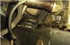
The following photo shows an example of incorrect adjustment of the main pair and the presence of roughness at the contact points:

After adjusting the rear axle, there should be no axial play in the bearings of the main drive pinion and in the bearings of the differential of the main drive. Axial clearance in axle bearings is the main cause of axle noise and jamming due to the destruction of the teeth in the main pair. There are very few craftsmen who know how to correctly adjust the main pair of the bridge. The instructions on the Internet are not very helpful, since the process is iterative, requiring not only ability, but also experience. We specialize in adjusting drive axles. People come to us from other cities on the recommendations of our clients for the bulkhead of driving bridges and checkpoints, including foreign cars. Drive axles, aluminum and UAZ tuning are our competitive advantage.
Oil change
The UAZ Patriot transmission should be filled with the highest quality oil that you can afford. Too little quality can flow through poor quality oil seals.
Very often in the rear axle over time, due to moisture entering it, the oil turns into a thick, non-flowing slurry. A simple oil change in such a bridge does not have the desired effect. If you are unsure, remove the axle and axle cover and clean the axle. Do not have any illusions - if the breathers are not removed, if you have been driving on water, if a lot of time has passed, etc., then there is no longer oil in the bridge. Moreover, the slurry is not in the gearbox, but closer to the hubs. Those. rear axle wheel bearings are practically not lubricated.
Breathers. Conclusion of breathers into the engine compartment
Breathers on bridges must be led out into the engine compartment so that water does not get into the bridge under any circumstances. This is usually done using brake hoses and brake pipes. It is easier to use oil resistant hoses.
At the end of the tubes under the hood, a plastic filter for fine fuel purification from the classics is installed so that dust does not get into the bridge. In this case, the end of the tube is bent down so that water does not enter the bridge even if the car goes into the water more than the location of the end of the tubes.
On cars with a compressor, during extreme operation, excessive air pressure is sometimes created in the transmission - as it were, the bridges, the box and the transfer case are inflated from the inside. This completely excludes the ingress of water and dirt inside and well lubricates the oil seals in places of friction.
Sometimes an expansion tank with a balloon is installed at the end of the tube to create volume. In this case, the connection of the inner space of the bridge with the atmosphere is completely closed. When the volume of air in the bridge changes during heating and cooling, the balloon inflates or contracts.
If you drove through a ford more than 30 cm deep, then you should immediately (on the same day) change the oil in the transmission - this is the manufacturer's instructions. Draw conclusions.
Wheel bearing adjustment
Adjust the wheel bearings of the spicer axle in the following sequence:
- Jack up the vehicle from the side of the wheel whose bearings are to be adjusted.

- Bend back the tab of the lock washer 6, unscrew the lock nut 7 and remove the lock washer.
- Loosen the nut 4 of the bearing adjustment 1 / 6-1 / 3 turn (1-2 sides).
- Turning the wheel by hand, check the ease of its rotation (the wheel should rotate freely without touching the brake pads on the disc or drum).
- Tighten the wheel bearing adjustment nut. Tightening torque 30 - 40 Nm (3.0 - 4.0 kg / cm). When tightening the nut, turn the wheel to correctly position the rollers on the raceways of the bearing rings and press the key knob smoothly, without jerks.
- Install the lock washer, screw on and tighten the lock nut. Tightening torque 30 - 40 Nm (3.0 - 4.0 kg / cm). Install the lock washer with the inner tab in the groove of the trunnion. If there are even minor cracks on the tab of the lock washer, replace the washer.
- Check bearing alignment after tightening the lock nut. When properly adjusted, the wheel should rotate freely without binding, noticeable axial play, or rolling.
- Bend one tab of the lock washer to the face of the nut and the other to the face of the locknut.
- Insert the axle shaft of the rear axle or put the clutch for disengaging the wheels of the front axle, clean the threaded part of the bolts from residual sealant, degrease and apply a new layer of sealant, tighten the bolts.
Finally, check the correctness of the bearing adjustment by observing the heating of the wheel hubs after driving.
If the hub heats up strongly (the hand does not tolerate heating), loosen the nut 1/6 turn (1 edge), observing the sequence and rules outlined above.
When checking the bearing adjustment for heating, do not use the service brakes, as in this case the hubs can be heated from the discs and brake drums.
A source
uaz-tuner.ru
kulibinsclub.ru
avtosteh.ru
Design features Possible malfunctions of the front axle, their causes and remedies Replacing the oil seal of the drive gear shaft of the front axle reducer Removing and installing the wheel cut-off clutch Removing and installing the axle shaft Replacing the oil seal of the front axle half shaft Removing and installing the main gear of the front axle Disassembling and assembling the front axle differential Adjusting the bearing ...
Figure: 6.4. Main gear: 1 - bolt; 2, 33 - spring washers; 3 - driven gear; 4, 24 - semi-axes; 5 - an adjusting ring; 6, 22 - bearings; 7 - spacer sleeve; 8 - outer cage of the outer roller bearing; 9 - roller bearing; 10 - a thrust ring; 11 - oil seal; 12 - reflector; 13 - flange; 14 - washer; 15 - nut; 16 - bridge housing; 17 - adjusting ring ...
 Replace the oil seal if oil leaks from under the gearbox flange. Note Oil leakage can also be caused by an excess of oil in the crankcase or a clogged breather. You will need: socket head "27", wrench, flat-blade screwdriver, torque wrench. 1. Brake the car with the parking brake, place stops under the rear wheels of the car. Raise ...
 The wheel clutch is removed to replace it or gain access to other units. You will need: wrench "14", flat-blade screwdriver, external circlip remover. 1. Unscrew the three fastening screws ... 2. ... and remove the clutch cover. 3. Remove the six bolts securing the wheel clutch and remove it. 4. You ...
 The half-shafts of the front wheels are removed for replacement in case of damage, failure of the constant velocity joints (SHRUS) or to gain access to other units. 1. Brake the car with the parking brake, place stops under the rear wheels of the car. Raise and place the front of the car on supports, remove the wheel. 2. Remove the brake disc (see "Replacement ...
 Replace the oil seal if you find oil leakage from the steering knuckle. You will need a flat-blade screwdriver. Note Oil leakage can also be caused by excess oil in the crankcase or a clogged breather. 1. Brake the car with the parking brake, place stops under the rear wheels of the car. Lift and place the front of the car on supports, remove the ...
 The main gear is removed for repair or replacement. You will need: keys "for 10", socket head "for 19", "for 27". 1. Brake the car with the parking brake, place stops under the rear wheels of the car. Raise and place the front of the car on supports, remove the wheels. 2. Unscrew the plug and drain the oil from the front axle (see "Changing the oil in the front ...
6.5.9 Dismantling and assembling the front axle differential
You will need: keys "for 14", "for 17". 1. Remove the differential assembly with the driven gear (see "Removal and installation of the main drive of the front axle"). 2. Press the bearings off the axle of the differential box. 3. Remove the ten bolts securing the driven gear to the differential and remove the driven gear. 4. Remove the eight differential carrier cup bolts and separate the cup. 5. Extract ...
Adjust the final drive bearings in the following order. Figure: 6.4. Main gear: 1 - bolt; 2, 33 - spring washers; 3 - driven gear; 4, 24 - semi-axes; 5 - an adjusting ring; 6, 22 - bearings; 7 - spacer sleeve; 8 - outer cage of the outer roller bearing; 9 - roller bearing; 10 - a thrust ring; 11 - oil seal; 12 - reflector; 13 - flange; 14 - shai ...
 The front axle is removed to replace its beam or when all parts are completely worn out, when a partial repair becomes impractical. You will need: keys "17", "19", "22", "24", "27", suspension springs. 1. Brake the car with the parking brake, place stops under the rear wheels of the car and jack up the front of the car. 2. Loosen the fastening nuts of the front ...
For UAZ Patriot and UAZ Hunter cars, as well as all models based on them, front and rear single-stage drive axles of the Spicer type with a one-piece crankcase, named after the American engineer Clarence Spicer, are installed
Exterior view of the front axle "Spicer"
Spicer-type bridges began to be installed on UAZ-3160 and UAZ-3162 Simbir vehicles, instead of Timken bridges. But on these cars, as well as on the first models of UAZ Hunter, "narrow" bridges with a width of 1445 mm were installed.
UAZ Patriot began to install "wide" bridges with 1600mm gauge.
Design features
The axle casing consists of a one-piece cast crankcase of the final drive, casings (stockings) of the axle shafts pressed into it and a stamped crankcase cover.

The absence of a split in the transverse plane of the axle gives the structure high rigidity, the unloaded connection of the cover and the crankcase reduces the likelihood of leakage along the joint, and the placement of the main gear and differential in a single crankcase ensures high precision of engagement and more favorable conditions for the operation of bearings.
Thanks to all these design features, the actual life of the bridges has increased significantly. In addition, now, to access the main pair and the differential, it is not necessary to remove and "half" it - just remove the cover.
To reduce warpage of the driven gear during its heat treatment and, as a result, reduce noise, increase the reliability and durability of the final drive, the thickness of the "substrate" of the driven gear was increased by 8 mm. However, this measure led to a change in the left differential cup. But, the new differential can be used on the old single-stage axles with a split crankcase, provided that an expansion ring is installed on the spike of the cup.
Spicer bridges are unified with old single-stage bridges in a number of other details. These are differential bearings, rear axle half-shafts and almost all parts of the hub assemblies. The front bearing with a double seal (469-2307086-03) and a new double-lip collar of the drive pinion flange are unified with similar parts of the U-shaped ("military") axles manufactured by JSC "UAZ".
As for the front driving and steering axles, here, in addition to the above points, it should be noted new joints of equal angular velocities ( CV joint) like " Beerfield", Which are much more durable than old-style hinges (" Weiss"). At present, all Spicer and Timken bridges are equipped with such hinges. It will not be superfluous to recall that to lubricate the Birfield hinges, a special SHRUS-4 grease is used, which should not be put into the entire inner cavity of the steering knuckle, as before, but only into the hinge itself. The use of other types of lubricants, including the traditional Litol-24, is unacceptable. During operation, adding grease to the joint is not required. The inner cavity of the steering knuckle is still filled with Litol-24 grease.

Main gear:
1 - bolt; 2, 33 - spring washers; 3 - driven gear; 4, 24 - semi-axes; 5 - an adjusting ring; 6, 22 - bearings; 7 - spacer sleeve; 8 - outer cage of the outer roller bearing; 9 - roller bearing; 10 - thrust ring; 11 - oil seal; 12 - reflector; 13- flange; 14 - washer; 15 - nut; 16 - bridge housing; 17 - an adjusting ring of the driving gear; 18 - outer race of the inner roller bearing; 19 - inner roller bearing; 20 - oil deflector ring; 21 - shaft with a driving gear; 23 - differential bearing adjusting nut; 25, 39 - right and left parts of the differential housing; 26 - bolt; 27, 40 - support washers of the semi-axle gears; 28, 43 - semi-axle gears; 29, 45 - axles of differential satellites; 30, 41, 44, 46 - differential satellites; 31, 38 - differential bearing caps; 32 - retainer for differential bearing adjusting nut; 34, 36, 37 - bolts; 35 - cover of the main gear housing; 42 - gasket for the cover of the final drive housing
Spicer bridges produced by the plant have a gear ratio of 4.111 (37: 9) or 4.625 (37: 8). Axles with a gear ratio of 4.111 are installed mainly on cars with gasoline engines, and with a gear ratio of 4.625 - on cars with diesel engines.
Front wheel hub

Front wheel hub UAZ with disc brakes, but without ABS
Front axle steering knuckle

Steering knuckle and hub.
1 - leading flange with a plug; 2, 10, 25 - gaskets; 3 - a hub with a brake disc; 4 - hub bearings; 5 - wheel bolt; 6 - brake disc shield; 7 - heat-insulating shield of the ABS sensor; 8 - pin; 9 - steering knuckle body; 11 - clamping sleeve; 12 - kingpin; 13 - pivot liner; 14-bracket for fastening the ABS harness; 15 - spring; 16 - outer sealing ring; 17 - inner sealing ring; 18 - hinge; 19 - ball bearing; 20, 28 - thrust washers; 21 - pivot support; 22 - outer cage of the oil seal; 23 - pad; 24 - nut; 26 - impulse disk; 27 - cuff; 29 - retaining rings; 30 - lock washer; 31 - nuts; 32 - lock washer
UAZ steering knuckle assembly diagram:

1 - brake disc shield; 2 - amplifier of the heat-insulating shield of the ABS sensor; 3 - heat-insulating shield of the ABS sensor; 4, 18 - bolts; 5 - impulse disk; 6 - hub; 7, 12 - bearing; 8 - lock washer; 9 - nut; 10 - lock washer; 11 - lock nut; 13 - thrust washer; 14 - cuff; 15 - pivot of the steering knuckle; 16 - gasket; 17 - steering knuckle joint; 19 - ball bearing; 20 - axle shaft casing
Adjustment of axial clearances in the front and rear axle Spicer
The axial clearance in the bearings of the main gear drive gear is not allowed, since if it is present, the gear teeth wear quickly and the bridge may jam. Axial clearance is checked by swinging the drive gear by the propeller shaft mounting flange.
Front axle "Spicer". Camber, convergence
The front axle is a steering axle. To facilitate driving, the front steering wheels have camber ( not adjustable) in the vertical plane and convergence in the horizontal plane.

Convergence of wheels. AND< Б на 1,5-3 мм.
To return the wheels to the middle position, the pivots of the steering knuckles are inclined in the longitudinal and transverse planes.
Positive camber is the deviation of the top of the wheel from the vertical plane outward.
The camber angle at the Spicer axles is a \u003d 1 ° - 30 ". Wheel camber affects tire wear. When camber is up to 2 °, the wear will not be very large. camber gradually decreases to zero, and then the deflection of the wheels moves towards negative camber, which worsens wheel steering.

As a result of the inclination of the wheels during collapse, forces arise that tend to return them in different directions when driving. Lateral wheel slip appears, which increases tire wear and makes driving difficult. To eliminate the harmful effects of camber, the wheels are installed with toe-in. At the same time, the distance between the rims of the wheels at the level of the front axle at the front is several millimeters less than at the rear.

The longitudinal tilt of the king pin (KASTOR) is designed to stabilize the steered wheels in the middle position, but its effect is noticeable only at high speeds with significant centrifugal forces. The stabilizing moment and the angular speed of the wheel when returning to the neutral position serve as the measuring wheel stabilization when the car exits a turn.
Maintenance
Maintenance of the Spicer bridge is reduced to maintaining the oil level in the crankcase and periodically replacing it, monitoring the condition of all seals and axle mountings and timely elimination of the resulting axial clearances in the gear and differential bearings.
The details of the maintenance and repair operations for the Spicer bridges are described in the Manual for the maintenance and repair of the UAZ Patriot vehicle IR-05808600.050-2005. Third edition. 2007
Bridges UAZ Patriot their device and maintenance is a rather interesting topic among UAZ producers. Especially many are worried about front axle UAZ Patriot, because structurally the front axle is more difficult to repair and install. Today we will tell you more about the bridges of the modern Patriot.
First, a little history of UAZ driving axles and the arrangement of these transmission elements. Initially, the bridges of UAZ off-road vehicles were "military" and "collective farm", they decently differed in their arrangement among themselves. Among lovers of SUVs, it is the "military" types of bridges that are valued. But on the current UAZ Patriot, completely different bridges are installed, which have a number of features, although some parts are interchangeable with old bridges.
Modern Patriot bridges of the "Spicer" type now they come with a track increased to 1600 mm. After all, the old bridges were only 1445 mm and did not fit the rather wide Patriot. Also, the main gear housing was changed in the design, which is closed with a removable steel cover, and to access the main gear and differential, you no longer need to remove and disassemble the axle, you can simply remove the cover.
The device of the front and rear axles "Spicer" are similar, and we will talk about the features below. So the bridge case
consists of a one-piece cast crankcase of the main gear, casings (stockings) of the axle shafts pressed into it and a stamped cover. The absence of a connector in the transverse plane of the bridge gives the structure high rigidity (continuous type of bridge). Placing the main gear and differential in a single crankcase ensures durability and high precision of the main pair teeth meshing.
A schematic of the Patriot front axle is shown in the first picture at the very top of the article. The main feature of the bridge can be considered the presence of constant velocity joints. After all, the front wheels, in addition to rotation, should also turn. Initially, Weiss type CV joints were used, but they were abandoned. Due to the design features, the steering angle did not exceed 27 degrees, which affected the vehicle's maneuverability. Therefore, new CV joints of the "Bearfield" type are now being installed, which provide a 32-degree turn and more durable, due to a more uniform load on the elements of the pivot joint.
Only “SHRUS-4” is used as a lubricant for the UAZ Patriot SHRUS, the previously widely used LITOL-24 grease is no longer suitable for these purposes.
The Patriot rear axle can be seen in the schematic below.

Usually the rear axle "Spicer" does not cause problems for SUV owners. The main thing is to constantly monitor the oil level in the axle housing. Since the bulkhead of the axle or replacement of the final drive with a differential is a lottery. It's pretty easy to run into raw metal and then drive with a constantly humming transmission.
The main tips for using Patriot bridges quite simple - you should not drive with the front axle connected on a dry, good road, this leads to increased fuel consumption and wear of the transfer case. You should not allow one of the wheels to slip for a long time if you are stuck, this can lead to accelerated wear of the axle. But when driving with an ambient temperature of minus 30, it is better to connect the front axle.
Recall the serial UAZ Patriot does not have a cross-axle differential lock... That is, if the front right wheel is stuck in the mud, and the front left wheel hangs in the air, then only the one that is free will rotate. The same is with the rear wheels. In order not to get into a stupid situation, real off-road lovers re-install the interwheel lock on their own. Today there are several types of locks for every taste and wallet.
A car with all-wheel drive UAZ Patriot has two drive axles, and the front axle is not connected through a clutch or electronic systems. The design provides for the selection of torque through the transfer case and further to the main gear of the axle. Various photos and diagrams of both the front and rear axles can be viewed not only in catalogs, but also on sites on the Internet.
Design features, device
Car on the lift
There are no big differences in the device of the driving axles. The front axle of the UAZ Patriot has a single-stage design. This is reflected in the transmission of torque through the final drive and differential.
In the front hollow beam, there are two axle shafts that receive rotation from the driven gear of the main drive and transmit it to the hub. The half shafts transmit rotation through the CV joints.
When using the front axle, you can engage the wheels by turning on special couplings, also called hubs.
Possible malfunctions and their manifestation
Despite the simplicity, due to the high load or violation of the operating rules, malfunctions may occur that are easy to diagnose.
The front axle is characterized by the following malfunctions:
- Increased noise during bridge operation. This device malfunction can be caused by:
- violation of adjustment and production of differential bearings;
- incorrect adjustment of bearings, production of gears in the design of the main gear reducer;
- low oil level in the axle housing.
- The increased noise level during car acceleration and braking is due to:
- violation of the meshing or clearance of the main gears;
- increased bearing clearances due to lack of adjustment or as a result of wear.
- The knocking noise when the car starts to move is caused by wear on the pinion axle in the differential mechanism.
- Lowering the oil level:
- loss of elasticity by the front axle oil seal;
- wear of the seals of the internal hinge;
- poor fastening of the bridge cover.
- Noise while driving when cornering will be due to wear on parts of one or more constant velocity joints.
It should be noted that malfunctions are similar to those that can occur in the rear axle parts. Taking into account the simple structure of the bridge, difficulties with repair, as a rule, do not arise.
The sequence of actions for different types of repair

Bearing adjustment
In order for the UAZ Patriot bridge to work reliably for a long time, after completing the necessary repair steps, it is necessary to correctly adjust the bearing clearances. Operations are performed in a specific order.
- An adjusting ring is selected for the bearing of the main drive shaft. The thickness of the ring is determined by the difference in length from the imaginary line of the center of the axle shafts to the outer edge of the bearing with the thickness of the bearing itself.
- After installing the adjusting ring and the drive gear, check the torque while rotating the shaft. It should not exceed 1.0-2.0 Nm.
- Using a similar algorithm, an adjusting ring is selected for the driven gear.
- When installing the differential, the bearing clearances of the axle shafts are set with adjusting nuts.
- After mounting the mechanism, the torque at the output should be no more than 0.42 Nm when rotating behind the drive gear.
- A necessary operation to control the correctness of the adjustments made is to check the absence of backlash, as well as the engagement of the gears of the mechanism along the contact patch. To do this, rotate the driven gear, controlling the contact point of the teeth.

Bridge tuning
The engagement should not be superficial or excessively deep, for which purpose adjusting rings of the required thickness are installed under the bearings.
You will also be interested in:

The number of people killed in road accidents on the roads of Russia is high. And often the cause of fatal ...

The suspension of a vehicle is one of the most important parts subject to great stress ...
What do you know about power steering oil? Chances are, most of the information you got from ...

Daewoo Nexia is a car that was developed by the German company Opel, but then it ...
Drivers develop a good habit over time - before getting into ...

