


The time has passed when the word computer was spoken aloud by a few people. Today, this device is found in almost every home and has become a standard device in automotive technology. He became an indispensable assistant for drivers, as he took over the functions of monitoring the operation of most modern units. vehicle.
PURPOSE AND BASIC FUNCTIONS
Cars manufactured in Russia are equipped with such a device. So, for example, the regular on-board computer became the firstborn in the family of VAZ cars. In simple terms, it is a car directory on wheels. The driver needs it in order to know what is happening both inside the car and outside.
WHY IS IT INSTALLED IN A CAR
The first versions performed few functions, these were:
- Control over the availability of fuel in the vehicle and the distance that can be covered by it. This will help the driver make the right decision to refuel or stop driving in time;
- Monitors the worker in the motor and helps prevent overheating.
Using more expensive versions computers, allow you to diagnose individual components and assemblies of the machine.
They are endowed with the ability to decipher the fault codes that the controller issues, and this allows the driver to:
- To be promptly informed about the problems that have arisen in a particular system of the machine, and to respond correctly to this. Eliminating the problem in its "bud", eliminates expensive repairs;
- Get savings from car operation.
ABOUT ITS FUNCTIONS
On-board computers VAZ 2114 are endowed with and perform the following basic functions:
- They display information about which indicators have instantaneous parameters;
- Display of current information on the information panel;
- Routing parameters are reported. They mean information about mileage, average fuel consumption, travel time and other data;
- Ability to read error codes and diagnose a car engine. This allows you to receive information about all the problems of the power unit without lengthy consultations with "specialists".
Some of the models have additions to the main functions, which may include:
- Information about the timing of the next service of the machine;
- Some major feature adjustments;
- Control over the insurance period;
- Availability of organizer functions;
- The ability to set the parameters at which it will be possible to turn on the fan in the cooling system.
ON THE PRINCIPLES OF THE FUNCTIONING OF SUCH SYSTEMS
VAZ 2109 carburetor machines were equipped with devices with router functions. Installation of injection power plants VAZ 2114, VAZ 2115 and other models, required the use of a completely different type of device. Most of his functional activities are devoted to diagnostics and operation control of almost all devices and systems of vehicles.
The work of the BC VAZ 2114 is based and has the following operating principle:
- Receiving signals from sensors through the control unit, processing them and issuing messages to the display, as well as the possibility of making adjustments for other systems;
- Processing signals from systems that are not controlled by the controller. In case of emergencies, the corresponding icon is displayed on the information board, and a sound signal is also given.
HOW TO USE SUCH DEVICES: BRIEF INSTRUCTIONS
For the installed devices, an instruction for the standard on-board computer VAZ 2114 is attached. It informs and instructs the car owners in detail about what to do in a given situation. Let's talk about how to use the VAZ 2114 on-board computer. To use it correctly, you must:
- These trip computers are highly sophisticated electronic devices capable of performing over 500 different functional duties. All this requires the driver to carefully study this device. The instruction manual helps with this. It is good to study it when the information board is on;
- The most attention in the study should be paid to the icons and symbols of emergency commands.
- has buttons that control the work of the BC VAZ 2114. You need to study and remember the rules for working with them.
When choosing such devices, there are no special requirements for them. The selected model must support programs 2114. Today, the cost of a VAZ 2114 on-board computer can be from 1500 to 4000 rubles. You can find even more of these products in online stores.
It makes no sense to memorize all possible error codes displayed on the information board. They do not need to be recited by heart like in school. We live in the age of Internet technologies, find the designation of these error codes, print and carry with you in the car. If you see the symbols on the information board, you can quickly make the right decision. Continue driving or call for technical assistance. Unfortunately, there are times when the on-board computer erroneously issues a danger signal. The culprit in such cases may be a sensor or the processor itself. No one is immune from emerging electronics malfunctions, but in most cases, the board signals reliable information.
The main possible error codes on this machine will be shown below.:
- 2 - voltage of the on-board network is exceeded;
- 3 - problems with;
- 4 - malfunction with a sensor that monitors temperature regime motor;
- 5 - incorrect signal from the outside air temperature sensor;
- 6 - signal about overheated motor;
- 7 - too low a car lubrication system;
- 8 - problems with the braking system;
- 9 - undercharged battery.
You should react to codes 4, 6 and 8, which must be eliminated and only then continue further movement. After elimination, a processor reboot is required. Errors are cleared by pressing and holding the daily mileage key.
WHAT TO DO WHEN THE BK STOPS OPERATING
It sometimes happens that the on-board computer does not work. What, then, do experts advise to do? The first step is to decide on. If it does not show any "signs of life" at all, F3, which is installed in the power supply circuit of the VAZ 2114 processor. If its replacement did not bring "revitalization" to its work, check the connection connectors.
It makes no sense to describe the essence of the repair process for such a complex electronic product, since for this, in addition to having the necessary devices and tools, it is also necessary to have education in the field of electronics.
The on-board computer (BC) is an automated vehicle control system. There are several types of BC, to find out what type is installed on your car, you need to read the contents of the sticker on the device. Depending on the type of engine, the appropriate types of BC are selected. For injection engines Most of all automated control systems are produced in the car. The most versatile on-board computer for the VAZ 2114 can be considered multitronics.
Purpose of the on-board computer
Those who have installed an on-board computer in their car, and this is the name of this innovation, which provides additional control, believe that its functions can satisfy the needs of even an avid car enthusiast. At first glance, this electronic device demonstrates the characteristics that were presented before it on the control panel of various VAZ models, including the 2114th. There is a clock in every car, as well as a speedometer (speed meter), a tachometer (shows the engine speed), an odometer (responsible for the mileage).
They, however, quite harmoniously flaunt in front of the driver's eyes, decorated in the proper form. Yes, and other parameters are present here: how much fuel is in the tank, there may even be thermometer readings that display indicators of both external and internal air conditions. Everything is done according to the highest standards of auto design. But control systems (on-board computer) are not just different indicators brought together on one screen.
Differences between BC and the control panel
Experienced drivers know that the speedometer simply converts the engine speed into speed, and as soon as the wheels are changed to a larger diameter, the speed will increase, although the indicator will work in the old-fashioned way. In order not to get into a mess at the next traffic police post, you cannot do without a BC. But much remains unaccounted for by simple clamps, but in long journey factors such as actual and average fuel consumption, information about the mileage already covered, the amount of fuel used, etc., will be quite appropriate. These parameters of the VAZ 2114 can be calculated, but before that is the driver, who is primarily obliged to follow the road, and not deal with calculations.
"Smart" car 2114 itself will monitor that the car does not overheat in the heat, and the most advanced of the on-board computers - even about the danger of ice formation in frosts. The computer will also report the voltage inside the engine system. With such an assistant, the trip will be much safer, over short or long distances. The main thing is not to ignore the computer warning signals.
It may seem that an indicator appeared on board, which began to count indicators. But in fact, the data on the operation of the car's equipment were known before, they were simply not displayed in front of the driver. However, why was it necessary to transform the salon passenger car into the cockpit? Connecting the on-board computer (on-board computer) to all sensors existing inside the car, processing the received data and submitting them in a form convenient for the driver - this is the main task that is assigned to the BC.
The task of the On-Board Computer is not only to collect information from vehicle sensors, but also to process it, correct, analyze and display it in a form convenient for the driver.
Connecting On-Board Computer
The VAZ 2114 car model is already equipped with a prepared place for installing an on-board computer. As a rule, the computer "Multitronics" or "State" is very suitable for her. Many motorists, who have experienced all their charms, recommend opting for these brands. Moreover, there are variants of this device with a color screen - for amateurs. But this is nothing more than an additional convenience and, apart from "beauty", is no different from its predecessors.
To connect the on-board computer, you will need to perform some mandatory operations:
- First of all, the device itself should be connected to the power supply. For this, direct current + 12V is used, which exists in the VAZ.
- In order for the BC to start automatically at the same time as the engine is turned on, the power used to ignite the engine must be connected to it. If you connect to an electrical source of side lights, the computer screen will "dim" a little, which is very convenient when it gets dark.
- It is imperative to connect the ground.
- Whether or not to send a signal from the fuel level sensor (FLS) depends on the model of the BC used. Some of them themselves theoretically consider how much of it has already been used, depending on the indicators of instantaneous fuel consumption and its initial presence in the tank.
- It also remains to connect the diagnostic line of the K-line controller.
If there is no pad in the on-board computer
As a rule, for all these procedures, it is enough to connect a standard four-pin connector with adapters that are provided with the on-board computers. In case it is missing, there should be no problems either. General nutrition can be "borrowed" from the cigarette lighter, autostart - from the ignition switch, "muffler / dimensions" - from the backlight of the same cigarette lighter, weight - from the body or again from the cigarette lighter.
To avoid any troubles during the above actions, a lot car battery worth turning off.
The signal from the fuel level meter (FLS) should be taken from the wire, according to the wiring diagram of a specific VAZ car, as well as connect the diagnostic line.
However, in the instructions attached to the bookmaker, everything is described in sufficient detail, therefore, strictly following it, it is rather difficult to make a mistake.
Even if the "bortovik" was received as a gift and perhaps without recommendations, then they can be searched on the Internet, including on the forums. But, as a rule, they are all standard and simply depend on their strict implementation.
A trip with a trip computer, as it is also called, will not surprise you on the road. The driver will be able to control the condition of the car on his own and once again go to the service station for diagnosis (a rather expensive procedure) there will be no need.
The regular on-board computer is designed to display the trip time, overboard temperature, speed, voltage in the on-board network, mileage, total fuel consumption for the trip, fault codes, clock and alarm clock.
Video instruction
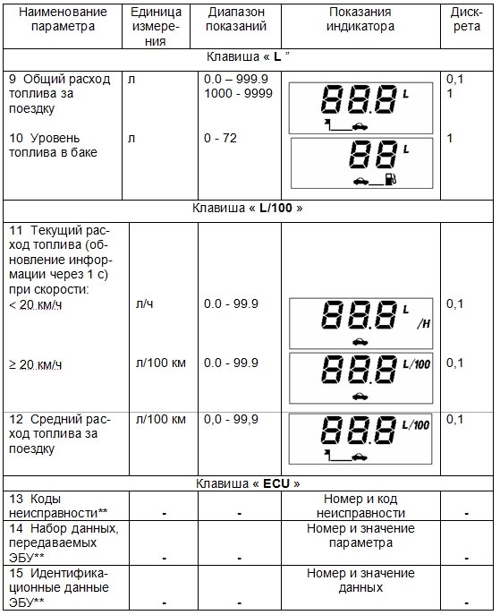
Screen indications
Parameters and sequence of switching computer display modes

Download instruction
Trip computer 2114-3857010 instruction
Sequencing:
- disconnect the battery terminals;
- dismantle the cover from the "tidy";
- open access to the connector responsible for diagnostics;
- remove part of the console;
- connect a meter piece of wire (see the image below);


Operating instructions for trip computer
VAZ 2113-15 (AMK-211501)
Passport РЮИБ.402253.507-01 PS
Route computer AMK-211501 (hereinafter referred to as the computer) is designed to process sensor signals and display vehicle movement parameters, fuel consumption, ambient temperature, on-board network voltage, time parameters, diagnostics electronic systems engine management (hereinafter referred to as ECM), as well as for detecting obstacles and indicating the distance to them when the car is moving in reverse (with a connected car parking device).
We ask you to carefully read this passport, which will allow you to fully use the performance of your computer. When buying, it is necessary to check the absence of external mechanical damage, the completeness, the presence and integrity of the factory seal, the correspondence of the serial number of the computer to the number indicated in this passport, as well as the passport, signed and stamped by the seller. The manufacturer may make minor design changes to the computer that do not worsen its quality and reliability, which are not reflected in this passport. on-board computer for vaz 2114 operating instructions Legal address of the manufacturer: Russia, 305038, Kursk, st. 2nd Rabochaya, 23, JSC "Schetmash".
ATTENTION: THE COMPUTER IS DELIVERED TO THE CONSUMER WITH A PROTECTIVE FILM ON THE GLASS OF THE COMPUTER PANEL, WHICH CAN BE REMOVED AT THE DESIRE OF THE CONSUMER.
1 Product basics and technical data
1.1 The computer is installed on VAZ 2108, VAZ 2109, VAZ-21099, VAZ-2115 cars (hereinafter - VAZ cars) with an engine carburetor type or equipped with ECM with an electronic control unit (hereinafter - ECU):
- M1.5.4,
- M1.5.4N,
- MP7.0 or January-5.1,
- gAZ-3110 cars,
- GAZ-3102 with engines equipped with ECM with ECU: MIKAS 5.4, MIKAS 7.1, 301.3763 \u200b\u200b000 01.
The computer can also be installed on other types of vehicles that provide signals for the vehicle speed and fuel consumption with the signal parameters given in Appendix A.
- fuel consumption sensor TU 4213-001-00225331-95 (hereinafter - DRT),
- vehicle speed sensor TU 4228-001-00225331-95 (hereinafter - DSA),
- external temperature sensor TU 4573-028-00225331-00 (hereinafter referred to as DVT),
- set of assembly parts RYUIB.402921.501 LLP (RYUIB.402921.501-02) (hereinafter - KMCH), purchased by the consumer (if necessary) separately.
A car with an engine equipped with an ECM must be equipped with a set of mounting parts RYUIB.402921.501 LLP (RYUIB.402921.501-03) (hereinafter referred to as KMCH1) and DVT produced by OJSC "Schetmash" to install a computer, purchased by the consumer separately.
The GAZ-3110 car with the ECU MIKAS 5.4, MIKAS 7.1, 301.3763 \u200b\u200b000 01 must be equipped with a set of mounting parts RYUIB.402921.501 LLP (RYUIB.402921.501-06) (hereinafter - KMCH2) produced by OJSC "Schetmash", purchased by the consumer separately.
To use the "Parking" function, the car must be additionally equipped with a car parking device РЮИБ.453688.501 manufactured by OJSC "Schetmash", purchased by the consumer separately. on-board computer for vaz 2115 instructions
1.2 The computer displays the parameters:
- current time of day;
- travel time excluding stops;
- total travel time;
- the calendar;
- alarm clock;
- current fuel consumption;
- average fuel consumption per trip;
- total fuel consumption for the trip;
- mileage on the remaining fuel;
- fuel level in the tank;
- mileage of the trip;
- average travel speed;
- overboard temperature;
- instant speed;
- on-board network voltage;
- the presence of an obstacle and the distance to it when the vehicle is reversing.
The parameters and sequence of switching the display modes of the computer are given in Appendix B. The computer receives and displays diagnostic information from the ECM and performs the following ECU diagnostic functions:
- - reading of codes of malfunctions; - reset of all accumulated ECU fault codes;
- - reading the set of parameters of the ECU; - reading the identification data of the ECU (the function is not available when selecting ECUs of the type MIKAS 5.4, MIKAS 7.1, 301.3763 \u200b\u200b000-01).
The computer receives information about the distance to an obstacle from the car parking device. The computer provides reception of signals from sensors installed in the car: DSA, DRT, DVT and fuel level sensor (hereinafter FLS). The parameters of the sensor output signals are given in Appendix A.
The computer is designed to work in a circuit direct current with a rated supply voltage of 12 V DC in accordance with GOST 3940 84.
Operating voltage range from 10.8 to 15.0 V.
Maximum current consumption of a computer with a supply voltage of 13.5 V and no sound signal in the operating temperature range, A, not more:
- when the ignition is off and there is no backlight voltage on contact "6" ………. ………………. …… 0.015;
- when the "backlight" mode is turned on ………. ………………. …… 0.160.
The operating range of the ambient temperature is from minus 4 0 to plus 60 o C.
Overall dimensions, mm, no more than …………………………… 238х50х56.
Weight, kg, not more than ……………………………………… .. ……………… 0.4.
2 COMPLETE SET
Trip computer AMK 211501 - 1 pc. Automobile route computer AMK 211501. Passport - 1 copy. Packing - 1 pc.
3 CONFIGURING THE ON-BOARD COMPUTER
3.1 Computer structure
A general view of the front panel of the computer is shown in Figure 1.
The computer has a case, on the front of which there is a panel with a liquid crystal indicator (hereinafter - the indicator) and ten keys for controlling the computer. On the rear wall of the case there is a connector for connecting the vehicle harness. Seven keys are used to select the desired group of functions and to select functions within the group and have the following designation:
"T", "KM / N", "KM", "L", "L / 100", "ECU", "N".
The "START" key is designed to determine the beginning of the trip and reset the accumulated parameters, to fix the parameter value in the correction mode and to set or remove the parameter control mode.
The "+" and "-" keys are used to increase or decrease the parameter value in the parameter correction mode and to view diagnostic information.
A map for switching display modes is given in Appendix B. When the ignition is off, the indicator displays the current time of day, the previously set alarm will give sound signal at the designated time.
To reset the alarm sound, press the START key.
Pressing any key other than the "-" and "+" keys turns on the indicator backlight. The type and combination of pictograms displayed on the indicator, as well as the symbols of the parameter units, determine the selected function.
The indication of the parameters: "Current time of day", "Travel time excluding stops", "Total travel time" is accompanied by a blinking dot.
When the alarm clock is set, the current time indication is accompanied by the bell symbol.
The computer monitors the following parameters:
- - maximum vehicle speed;
- - voltage of the on-board network;
- - vehicle mileage on the remaining fuel in the tank.

When the monitored parameter goes beyond the set value: the maximum speed is from 20 to 200 km / h, depending on the setting, the mileage on the remaining fuel is less than 50 km, the voltage of the on-board network is below 10.8 V or above 14.8 V, the bell symbol starts flashing and a sound signal is generated: for the first two parameters with a duration of 3 s and 15 s, there is a pause, the sound signal is repeated twice.
When the on-board network voltage deviates, the sound signal is generated with a delay of 10 s and has a duration of 5 s and a 5 s pause, the sound signal is repeated three times. The sound signal is accompanied by the display of the value of the controlled parameter. The sound signal is reset by pressing the "START" key. After the sound signal has been reset, the indication of the parameter that has gone beyond the set value is accompanied by a flashing bell symbol. When the parameter returns to its normal value, the alarm stops. To set or remove the parameter control mode, it is necessary to set or reset the “bell” symbol by pressing the “START” key in the monitored parameter indication mode.
For example, to set the overspeed control mode, use the "KM / H" key to enter the "Instantaneous speed" mode and use the "START" key to set the "bell" symbol on the indicator. Resetting or setting the sound signal of confirmation of pressing the keys is made in the mode of indication of the parameter "Travel time without taking into account stops" by pressing the "START" key.
Indication of parameters: "Average travel speed", " Average consumption fuel per trip ”,“ Mileage on remaining fuel ”is performed when the following conditions are met: the parameter“ Trip mileage ”is more than 1 km and the parameter“ Trip time without stops ”is more than 1 min, before these conditions are met, the indicator displays symbols“ - - - - ". To reset all accumulated parameters: "Travel time excluding stops", "Total travel time", "Total fuel consumption per trip", "Trip mileage", press and hold the "START" button for more than 4 s in the display mode of one of these parameters until a two-tone beep appears.
After resetting, it is necessary to check the state of the mode indicator (presence or absence of the "bell" symbol) in which the reset was performed, since it can change its state. If there is no DVT or a malfunction in its circuit in the "Temperature overboard" parameter indication mode, the "Co" symbols are displayed on the indicator.
3.2 Setting time parameters
Parameter readings correction mode:
- "Current time of day",
- "The calendar",
- The "alarm clock" is turned on and reset by pressing the "START" key.
The corrected digits of the parameter are indicated by flashing. The required parameter value is set with the "+" or "-" keys. If the "+" or "-" keys are held for more than 0.5 s, the autorepeat mode is activated. The clock is set according to the exact time signals as follows: in the indication mode of the “Current time of day” parameter, press and release the “START” key and on the sixth time signal the “H” key is pressed, while the digits of minutes and seconds are reset to zero. If the value of the "Current time of day" parameter coincides with the set value of the alarm clock, three melodic sound signals are emitted with a duration of 30 s each with a period of 1 min. Resetting the alarm clock setting is carried out as follows: in the “Alarm” parameter display mode, press and release the “START” key and then press the “H” key. In this case, the symbols “” appear in the digital digits, and the “bell” symbol is absent in the display mode of the “Current time of day” parameter.
3.3 Clock drift correction
To reduce the error of the watch, it is possible to introduce a correction factor. To do this, in the “Current time of day” parameter display mode, press and hold the “START” key for 2 s - the “C” symbol and the flashing value of the correction factor will appear on the indicator. Use the "+" or "-" keys to enter the required value of the coefficient and, by pressing the "START" key, exit the correction mode. Are the maximum values \u200b\u200bof the correction factor equal? 31. One unit of the correction factor is equal to the change in the clock rate by 0.35 s per day for positive values \u200b\u200band 0.18 s per day for negative values.
3.4 Setting the speed limit
The entry into the mode of setting the maximum speed is made by pressing the "START" key in the display mode of the "Average travel speed" parameter. In this case, a blinking value of the maximum speed appears on the indicator, when exceeded, an audible warning signal is generated. Changing the value of the maximum speed is carried out using the "+" or "-" keys in 5 km / h increments from 20 to 200 km / h. Exit from the installation mode is done by pressing the "START" key.
3.5 Operating modes of indicator backlight
When the instrument lighting is on, the backlight level is adjusted with the backlight control on the vehicle instrument scale. When the instrument lighting is off and the ignition is on, the backlight level is adjusted in the following sequence: in the “Total travel time” parameter display mode, press and release the “START” button. In this case, all single segments (icons) will be displayed on the indicator, which is a sign of the backlight level adjustment mode, and the number corresponding to the backlight level as a percentage of the maximum value will be displayed in digital digits. Use the "+" or "-" keys to set the required backlight level. Each time you press the keys, the backlight level changes by 5%. If the keys are held for more than 0.5 s, the autorepeat mode is activated. The set backlight level is retained until the next correction. To exit the adjustment mode, press the "START" key.
3.6 Setting the fuel level
Setting the fuel level table
The computer memory contains tables of FLS readings with a resolution of 3 liters (fuel level values \u200b\u200bat intermediate points are calculated by interpolation). Depending on the type of vehicle and the type of instrument cluster installed on the vehicle, for correct readings of the fuel level in the tank by the computer, it is necessary to set one of the fuel level tables recorded in the computer memory. Electromechanical instrument combinations can be installed on the car - they form an output signal of the fuel level with a maximum voltage of more than 5 V, or electronic instrument combinations that generate an output signal of the fuel level with a maximum voltage of up to 5 V (a distinctive feature of these instrument combinations is the presence of a liquid crystal odometer indicator) ... The procedure for setting the type of instrument cluster and the corresponding fuel level table is as follows:
a) disconnect the "Battery" circuit (remove the "-" terminal of the storage battery or disconnect the harness connector from the computer);
b) press one of the following keys to select the type of instrument cluster: - "L" instrument cluster of electromechanical type; - "L / 100" - electronic type instrument cluster; - "KM" instrument cluster of the GAZ-3110 car;
c) while holding the selected key, connect the "Battery" circuit (connect the harness connector to the computer) and after a time interval of 2 s release the key.
3.7 Calibrating the FLS
Due to the fact that a car's FLS has a large technological spread of parameters, to increase the accuracy of the fuel level readings, the computer provides a mode for correcting the FLS readings table (calibration).
ATTENTION! BEFORE BEGINNING TARING, MAKE SURE THE FUEL LEVEL SIGNAL IS CORRECTLY CONNECTED TO THE COMPUTER AND SET THE CORRECT TYPE OF INSTRUMENT COMBINATION.
The calibration procedure can be carried out at the request of the owner independently.
- To do this, it is necessary to drain the gasoline from the tank, leaving the minimum volume of fuel required for the operation of the gas pump (for VAZ cars it is 3 liters) - this volume is then taken as a zero level.
- Then enter the indication mode of the "Fuel level in the tank" parameter, press and hold the "START" key for 2 s, and a blinking number "0" will appear on the indicator.
- Press and hold the "L" key for 1 s until a sound signal appears to confirm memorization of information. After that, the indicator will show a blinking number "3".
- Pour 3 liters of gasoline into the gas tank using a measuring container, wait for the time required to set a constant fuel level, press and hold the "L" key for 1 s until a confirmation beep appears. The indicator will show a blinking number "6".
- Then, to continue taring, it is necessary to repeat the above procedure, each time adding 3 liters and then pressing the "L" key. In this case, it is necessary to ensure that the total amount of fuel in the tank corresponds to the value on the indicator for a particular calibration stage.
- To end the calibration mode after recording the last value of the fuel level, press the "START" button, turn the ignition off and on.
Note - The maximum possible value of the fuel level during calibration is 72 liters.
3.8 Computer operation in diagnostic mode
3.8.1 Reading fault codes
Entering the mode by the first pressing of the "ECU" key. The computer display will show the symbols "En.NN", where NN is the total number of fault codes accumulated in the computer's memory. The "+" and "-" keys select the malfunction number. For an ECU installed on a car of the VAZ family, the number of the malfunction is displayed on the indicator as a combination of symbols "EX.NN", where EX is the malfunction status, NN is the number of the malfunction. An example is E0. 1. Values \u200b\u200bof the status of the malfunction code for the MP7.0 ECU are shown in Table D.3.2. For an ECU installed on a car of the GAZ family, the malfunction number is displayed on the indicator as a combination of symbols "ENNN", where NNN is the malfunction number. If the total number of faults is 0, then the fault numbers are not displayed. Switching the indication to view the malfunction code and back (to view the malfunction number) is carried out by short (less than 1 s) pressing the "START" key. The keys "+" and "-" scrolls through all the fault codes. Possible meanings of trouble codes are given in Appendix D.
3.8.2 Resetting fault codes
All fault codes stored in the ECU memory are reset by pressing and holding for 2 s the "START" button in the mode of indication of codes or numbers of faults.
3.8.3 Selection of ECU type
The computer can be installed on vehicles with engines equipped with various types of ECUs. To select the type of ECU, enter the ECU parameters display mode (in the absence of communication with the ECU, the computer display will display the symbols "Ps.-" and the blinking "bell" symbol), press and hold the "START" key for 2 seconds until the indicator of the symbol "ECU" (ECU) and a flashing digit, which determines the type of ECU. Using the "+" or "-" keys select the required type of ECU and exit the mode by pressing the "START" key. To establish communication with a new type of ECU - turn off and then turn on the ignition. When choosing the type of ECU, the display shows:
- - "ECU.0" - M1.5.4;
- - "ECU.1" - M1.5.4N or January-5.1;
- - "ECU.2" - MP7.0;
- - "ECU.3" - MIKAS 5.4, MIKAS 7.1, 301.3763 \u200b\u200b000-01.
3.8.4 Reading ECU parameters
The mode is entered by pressing the "ECU" key. The indicator displays the symbols “Ps. 1 ", where Рс is the indication of the ECU parameter number, and 1 is the parameter number. The "+" and "-" keys select the parameter number. Switching the display to view the parameter value and back (to view the parameter number) is carried out by short (less than 1 s) pressing the "START" key. The keys "+" and "-" view all parameters. The list of ECU parameters displayed on the computer indicator is given in Appendix D.
3.8.5 Read ECU identification data (the function is not available when selecting ECU type MIKAS 5.4, MIKAS 7.1, 301.3763 \u200b\u200b000-01)
The mode is entered by pressing the "ECU" key. The display shows the symbols “Cu. 3 ", where Cu is the indication of the identification data number, and 3 is the data number. Switching the display to view the data value and back (to view the data number) is carried out by short (less than 1 s) pressing the START key. The keys "+" and "-" view all data. The list of ECU identification data displayed on the computer indicator is given in Appendix D.
3.9 Parking function
3.9.1 "Parking" function is performed only when a car parking device is connected to the computer. After turning on the reverse gear on the car and the ignition on, the indicator for 1 s appears “rdy” (short for English “ready”) and three short beeps sound. This means that the car parking device is intact and ready to work. If the obstacle is not detected, then the indicator in digital digits will display the symbols "- -". If the distance to the obstacle is in the range from 40 to 170 cm, then the distance in centimeters is displayed on the indicator. The direction to the obstacle is shown by the indicator symbols located below the digits: “< » — препятствие расположено слева от автомобиля; « > »- the obstacle is located to the right of the vehicle. If the obstacle is located in the center of the vehicle, both symbols are displayed.
3.9.2 Display of distance to obstacle accompanied by sound signals (when the “bell” symbol is set on the indicator), which become more frequent as the obstacle approaches. When the distance to the obstacle is from 170 to 90 cm, the frequency of occurrence of sound signals is 3 signals / s, from 90 to 60 cm - 5 signals / s, from 60 to 40 cm - 8 signals / s. When the distance to the obstacle is less than 40 cm, the sound signal becomes continuous and the display shows the inscription "StOP". Sound signaling when indicating the distance to an obstacle can be enabled (the indicator has a bell symbol blinking at a frequency of 1 Hz) or disabled (there is no bell symbol). The "bell" symbol is reset and installed by long pressing (more than 2 s) of the "START" button. When the “bell” symbol is set, the sound signal can be turned off until the end of the car's reverse mode by short (no more than 1 s and no less than 0.3 s) by pressing the “START” button - the “bell stops flashing” symbol.
3.10 Auxiliary modes of computer operation
3.10.1 Correction of fuel consumption readings. The computer readings of the fuel consumption parameters may differ from the actual values \u200b\u200bfor various reasons: the DRT error in vehicles with carburetor engine, deviation of pressure in the fuel rail or clogged injectors in vehicles with an engine equipped with an ECM.
To correct the fuel consumption readings, enter the “Current fuel consumption” display mode, press and hold the “START” button for 2 s until the flashing value of the correction factor appears on the indicator.
The nominal value of the correction factor is 100 (in percent). Changing the value of the coefficient is made with the "+" or "-" buttons, while the larger value of the coefficient corresponds to an increase in the fuel consumption readings, and to the lower one - a decrease in the fuel consumption readings.
To exit the correction mode, press the "START" key.
The correction factor can be determined as follows.
- Generate fuel to a certain value of the fuel level reading by the computer.
- Pour a measured amount of fuel into the tank - for example, 20 liters.
- Reset the total fuel consumption readings in the computer, for which, in the "Total fuel consumption" display mode, press and hold the "START" button for 4 s until a two-tone sound signal appears.
- Develop all the fuel filled up to the initial value of the fuel level reading.
- Note the total fuel consumption reading - e.g. 25 liters.
- Calculate the value of the correction factor: (20/25) x 100 \u003d 80.
- Enter the calculated value of the correction factor into the computer. The range of values \u200b\u200bof the correction factor is from 50 to 255.
- Then reset the fuel consumption reading.
3.10.2 Correction of voltage readings of the on-board network
The voltage readings of the on-board network are adjusted during the manufacture of the computer and after the repair of the computer associated with the replacement of the lithium battery.
To carry out the correction, you must:
- in the "On-board network voltage" display mode, press and hold the "START" button for 2 s until the blinking voltage value appears.
- Use the "+" or "-" keys to set the voltage value equal to that measured by a digital voltmeter on contact "3" of the computer block.
- Exit the correction mode by pressing the "START" key.
3.10.3 Checking the software version number
To control the version number of the computer software, press the "-" key and hold it to turn on the ignition. The indicator will display the symbols "ПР55" - where the first digit 5 \u200b\u200bdefines the type of computer (AMK-211501), and the second digit 5 \u200b\u200b- the number of the current software version (may differ upwards).
4. Installing a computer on a car
The names of signals and numbers of contacts of the computer plug are shown in Table 1.
Table 1
Signal name | Signal designation | Plug contact number |
| DRT output signal | ||
| Diagnostic bus "K-line" | ||
| Powering the computer through the ignition switch | ||
| DVT output signal | ||
| Powering the computer from a rechargeable battery | ||
| Switching on the backlight mode | ||
| Housing | ||
| FLS output signal | ||
| DSA output signal |
Description of computer pins is given in Table 2
table 2
| Fuel consumption signal input... Pulse signal of rectangular shape with frequency proportional to fuel consumption. Signal source - contact "2" DRT or contact "54" ECU (fuel injection controller) type М1.5.4 (January-5.1) or contact "32" ECU type МР7.0. | |
| Line "K" diagnostics... The contact is connected to the contact " M"Pads for diagnostics of VAZ cars or contact" 11 »Pads for diagnostics of GAZ vehicles. On this line, the computer exchanges information with the ECU. Data is transmitted as a series of pulses with an amplitude of low level (0 V) to the voltage of the on-board network. The line goes through the contacts " 9 "And" 18 »Of the control unit of the car anti-theft system (hereinafter - APS), which must be closed when it is absent or when the APS is not activated. The signal" K-line "from the car parking device is connected to this contact. | |
| Voltage signal input from ignition switch... The signal from the ignition switch is not a power supply to the computer, it informs the computer that the ignition is on. Used to measure the voltage of the on-board network. | |
Continuation of table 2
| DVT signal input... The computer sends along this circuit through an internal resistor a voltage of +5 V to the DVT, which is a thermistor, the second terminal is connected to ground. The sensor changes resistance depending on the temperature. | |
| Non-disconnectable voltage input... Constant power supply of the computer from the vehicle electrical system. The voltage is supplied through a fuse. | |
| Voltage input of the car instrument scale illumination circuit... The signal controls the brightness of the computer indicator backlight. | |
| Housing... The contact is connected to the vehicle body (ground). Contact voltage should be close to zero. | |
| Fuel level input... The contact is connected in parallel to the signal circuit of the car's FLS. The connection point is the vehicle instrument cluster connector. The signal voltage value is used to calculate the fuel level depending on the type of instrument cluster and the installed fuel level table. | |
| DSA signal input... A square-wave pulse signal with a frequency proportional to the vehicle speed. The signal comes from the contact "2" of the vehicle DSA or from the output of the instrument cluster (speed signal for the computer) or from the contact "9" of the ECU type M1.5.4, January-5.1, MP7.0. |
4.1 Installing the computer on a car with a carburetor type engine
The computer is installed in the car's interior in a special socket of the instrument panel (Figure 2) or in any place convenient for observation, taking into account the optimal viewing angle of the indicator corresponding to the position of the clock hand at 10 h 30 min (to the left and above from the perpendicular to the plane of the indicator), using bracket included in the KMCH. Connect the computer and sensors to the car according to Figure 2 using the KMCH (the positions indicate the elements of the KMCH):

- Screw V.M6-6g x14.58.016 GOST 1491-80 - 2 pcs
- Nut М6.58.016 GOST 5927-70 - 2 pcs.
- Washer 6.01.10.016 GOST 11371-78 - 4 pcs.
- Hose (outer diameter 14.5 mm) - 2 pcs.
- Clamp (inner diameter 14.5 mm) - 2 pcs.
- Nut (square) - 4 pcs.
- Screw V.M4-6g х12.58.016 GOST 1491-80 - 4 pcs.
- Washer 4.01.10.016 GOST 11371-78 - 8 pcs.
- Hose (outer diameter 10 mm) - 1 pc.
- Plug - 1 pc.
- Clamp (inner diameter 10.5 mm) - 2 pcs.
- Block X3 - 1 pc.
- Harness - 1 pc.
- Block X6 - 1 pc.
- Bracket - 1 pc.
4.1.1 Installing DSA
To install the DSA, you must perform the following operations:
- - disconnect the flexible shaft of the speedometer cable from the gearbox speedometer drive;
- - connect the DSA gearbox to the speedometer drive with a tightening torque of 6 to 8 Nm;
- - connect the flexible shaft of the speedometer cable to the output shaft of the DSA, having previously twisted the protective cap from the DSA.
4.1.2 Installation of DRT
To install the DRT, you must perform the following operations:
- - fix the DRT with fasteners pos. 1, 2, 3 on the car body in the engine compartment so that the “Exit” branch pipe of the DRT is located horizontally and below the fuel supply pipe of the carburetor at a distance of 10 to 20 mm;
- - remove the hose connecting fuel pump and a carburetor;
- - install the hoses pos. 4, connecting the fuel pump with the “Inlet” branch pipe of the DRT and the “Outlet” branch pipe of the DRT with the inlet union of the carburetor using fasteners pos. 5, 6, 7, 8;
- - remove the hose from the outlet fitting of the carburetor return line and install it on the “Return” branch pipe of the DRT;
- - put the hose pos. 9 with plug pos. 10, fixing it with fasteners pos. 6, 7, 8, 11, to the outlet fitting of the carburetor return line.
Note - When installing DRT on cars, in fuel system which there is no return line, the plug pos. 10 install DRT on the “Return” branch pipe.
4.1.3 Installing DVT
Install DVT inside the front bumper in a hole with a diameter of 12 mm on its lower plane on the left in the direction of the vehicle.
4.1.4 Connecting the computer to the car circuits
Connect the computer and sensors to each other and to the electrical equipment of a VAZ 2108, VAZ 2109 car in the following sequence:
- - open the hood of the car. Disconnect the wire from the "-" terminal of the storage battery;
- - remove the handles from the levers of the ventilation and heating system control panel. Unscrew the four self-tapping screws securing the instrument panel console overlay and take it away from the instrument panel;
- - remove the socket contacts of the red-black and orange wires from the block of the alarm switch (circuits "15/1" and "30") and connect them using the block pos. 12 ("X3") to the plug "X2" of the harness pos. 13. In place of the socket contacts removed from the block of the alarm switch, connect the socket contacts "5" (circuit "30"), "3" (circuit "15/1") of the harness pos. thirteen;
- - disconnect the two-terminal block of the car's wiring harness, white and black, suitable for the backlight lamp of the levers of the ventilation and heating system control panel, and connect the corresponding two-terminal blocks "X8", "X9" of the harness pos. 13 with white and black wires;
- - disconnect from the instrument cluster block the wire with the socket contact coming from the FLS, in accordance with the car's electrical circuit and connect it using the block pos. 14 ("X6") to the block "X5" of the harness pos. 13. In the socket of the instrument cluster block, instead of the removed wire, install the socket contact "8" of the harness pos. thirteen;
- - unscrew the two nuts securing the mounting block and lift it up until a gap is formed between its body and the rubber gasket, into which wires with two three-terminal blocks "X1" DRT and "X7" DSA are drawn from the passenger compartment into the air supply box. Replace and secure mounting block;
- - squeeze the rubber seal out of the hole in the center of the bulkhead of the air intake box and the engine compartment. Pass the sensor wires through the hole. Cut the rubber seal from edge to center, insert the sensor wire into the cut and install the seal in place;
- - connect the pads of the harness pos. 13 to sensors: block "X1" to DRT, and "X7" to DSA. Connect DVT to the AMR block of the harness pos. 13. Connect the nine-terminal block "XS" of the harness pos. 13. Insert the computer into the socket of the instrument panel. Depending on the type of instrument cluster, install the fuel level table in accordance with 3.6.
4.2 Installing a computer on a VAZ car with an engine equipped with an ECM
Connect the computer to a VAZ car with an engine equipped with an ECM, according to Figure 1 using KMCH1 (the positions indicate KMCH1 elements):
- Block X3 - 1 pc.
- Block X6 - 1 pc.
- Harness - 1 pc.
- Bracket - 1 pc.
Socket contact "1" of the harness pos. Connect 3 (fuel consumption signal circuit) to the vehicle's ECM harness block in accordance with the vehicle's electrical wiring diagram. Female contact "9" of the harness pos. 3 (circuit with a signal from the DSA), connect to the instrument cluster (if there is an output for connecting a computer) or to the car's harness block connected to the ECM. Plug "X10" harness pos. 3 is connected to the "M" contact of the vehicle diagnostic pads.
Note - If the APS is not installed in the car, then in the block of the APS control unit it is necessary to install a jumper between the contacts "9" and "18". Connect DVT, FLS, as well as power and lighting circuits in the same way as in 4.1.4 or in accordance with the car's electrical circuit and the purpose of the signals given in Table 1.
Connect the nine-terminal block "XS" of the harness pos. 3 to the computer.
Insert the computer into the socket of the instrument panel. Depending on the type of instrument cluster, install the fuel level table in accordance with 3.6.
On a VAZ-2115 car, produced after January 1, 2002, with an engine equipped with an ECM, the computer is installed in its regular place without using the KMCH1. The connection to the car circuits is made to the car harness block located in the niche for installing the computer.
Note - DVT installed in VAZ 2115 cars can only be used in conjunction with one of the devices: a combination of devices or a computer, while the DVT circuit from a device in which this DVT is not used must be disconnected.
4.3 Installing a computer on a GAZ-3110 car
Installation of a computer on a GAZ-3110 car with ECU MIKAS 5.4, MIKAS 7.1, 301.3763 \u200b\u200b000-01 is carried out using KMCH2, which includes the RYUIB6.640.786 harness and the RYUIB6.133.502-01 bracket. The computer is installed using a bracket in the passenger compartment in a place convenient for observation, taking into account the optimal viewing angle of the indicator, corresponding to the position of the arrow at 10 hours 30 minutes (to the left and above from the perpendicular to the indicator plane).
4.3.1 Installation work on connecting the computer to the circuits of GAZ-3110, GAZ-3102 vehicles using KMCH2 to carry out in accordance with Figure 3 as follows.
- Unscrew the four fastening screws and remove the instrument cluster trim by pulling it towards you.
- Mark and disconnect plug strips central switch light and headlight range control. Remove the four screws securing the instrument cluster.
- Turn the instrument cluster 90 0 and remove it from the instrument panel. Disconnect the vehicle harness connectors from the instrument cluster.
- Remove the socket contact "7" from the block of the vehicle harness "XP2", insert it into the block "X7", which is included in the KMCH2 and connect it with the block "X6" of the harness of the KMCH2.
- Insert the socket contact "6" into socket "7" of the socket "XP2". Remove the female contact "5" from the block of the vehicle harness "XP1", insert it into the block "X8" and connect it to the block "X5" of the harness KMCH2.
- Insert the socket contact "8" into socket "5" of the block "XP1". Remove the socket contact "2" from the block of the vehicle harness "XP3", insert it into the block "X3" and connect it to the block "X10" of the harness KMCH2.
- Insert the socket contact "3" into socket "2" of the socket "XP3".
- Remove the socket contact "10" from the block of the vehicle harness "XP3", insert it into the block "X11" and connect it to the block "X9" of the harness KMCH2.
- Insert the socket contact "9" into the socket "10" of the socket "XP3".
- Pull the wire from contact "2" of the block "XS" of the KMCH2 harness through the rubber seal into engine compartment vehicle to the diagnostic block located on the front panel to the right of the driver.
- Strip the insulation off a 5 mm long section of the wire (gray with red stripes) connected to the contact "11" of the diagnostic block at a distance of 3 cm from the contact. Using the wrapping method, connect the wire to the stripped area and insulate it with PVC tape.
- Install DVT into the 12 mm diameter hole on the front bumper of the car on the left in the direction of travel. Pull the “X4” connector with the wires through the rubber seal into the engine compartment and then connect to the DVT connector.

- Connect the short wire from the "X4" connector to the car body under one of the screws.
- Remove the two bottom screws securing the front ashtray panel.
- Open the ashtray and remove the two upper screws securing the front ashtray panel.
- Pull out the front ashtray panel towards you.
- Disconnect the cigarette lighter plugs.
- Connect the X2 pin block of the KMCH2 wiring harness to the cigarette lighter socket that is part of the car wiring harness.
- Connect the cigarette lighter plug to the "X1" socket of the KMCH2 wiring harness.
- Connect the “XS” block of the KMCH2 harness with the computer block. Install the cigarette lighter panel and instrument cluster in place. 4.3.2 Set the type of instrument cluster for GAZ-3110 vehicles in accordance with 3.6.
4.3.3 Select the type of controller ECU-3 (ECU.3) in accordance with 3.8.3.
4.4 Installing the car parking device
The car parking device consists of a control unit to which a pulse sensor R (right), a pulse sensor L (left) and a harness X1 are connected, as well as a bracket for attaching the sensors to the car (at the discretion of the consumer).
Install the control unit in the passenger compartment or in luggage compartment, the sensors should be installed on the rear bumper of the car.
Connect the car parking device to the car circuits in accordance with Figure 4.
- Route the parking device power harness wires from the control unit to the computer installation site. Remove the socket contact of socket "7" from the block "C" of the harness for connecting the computer to the car circuits, remove the housing "X6" from the socket contact of the black wire of the power harness of the car parking device and put it on the socket contact removed from the socket "C", connect the socket contact in the housing "X6" with plug "X5".
- Insert the female contact of the black wire of the power supply harness of the parking device into the socket "7" of the block "C".
- Connect the short red wire to the reversing lamp power circuit, leave the red wire with a female contact in the “X8” housing unconnected.
- Remove the socket contact of socket "2" (if available there) from the block "C", remove the housing "X7" from the socket contact of the green wire of the power harness of the car parking device and put it on the socket contact removed from the block "C", connect the socket contact in the housing "X7" with plug "X9".
- Insert the socket contact of the green wire of the power supply harness of the car parking device into socket "2" of the block "C".
- After finishing the installation operations, connect the plug-in connectors to the control unit in accordance with Figure 4.

5 List of possible malfunctions and methods of their elimination
Scroll possible malfunctions and methods for their elimination are shown in Table 3.
Table 3
Malfunction name, external manifestation and additional symptoms | Probable cause of failure | Troubleshooting method |
| No indication of the "Current time of day" parameter when the voltage of the "Battery" circuit is connected ("thirty") | "five" computer pads | |
| After turning on the ignition switch, only the indication mode of the parameter "Current time of day" | Contact circuit malfunction "3" computer pads | Check wires and their connections, replace damaged wires or contacts |
| Malfunctions in computer readings | Unreliable contact in the computer wiring circuits | Check and restore a reliable contact in the wire connection circuit |
| Flashing numbers on the indicator | The mode of correction of one of the parameters is on | Press the " START» |
| There is no indication of the "Current fuel consumption" parameter, and the readings of the "Total fuel consumption per trip" parameter do not increase | Contact circuit malfunction "one"computer pads, no signals from the DRT or fuel injection controller | Check wires and their connections, replace damaged wires or contacts and, if necessary, sensors |
| There is no indication of the "Instantaneous speed" parameter, the indication of the "Current fuel consumption" parameter only in l / h at a speed of more than 20 km / h | Contact circuit malfunction "9" computer pads, no signal from DSA | Check the wires and their connections, replace damaged wires, contacts or DSA |
| The voltage readings of the on-board network differ significantly (downward) from the voltage on the battery | Large voltage drop at the contacts of the ignition switch | Clean the ignition switch contacts |
6 Transport and storage
The computer is transported by any type of transport that ensures its safety from mechanical damage and atmospheric precipitation, in accordance with the rules for the carriage of goods in force for this type of transport. The transportation conditions for the computer correspond to group C GOST 23216 78 in terms of mechanical effects and group 2 C GOST 15150 69 in terms of the impact of climatic factors. The computer should be stored in the manufacturer's packaging under 2 C conditions in accordance with GOST 15150 69. The period of transportation of the computer from the manufacturer to the consumer should not exceed 9 months from the date of manufacture of the product. The count is based on the product labeling.
7 Manufacturer's warranty
The manufacturer guarantees the compliance of the computer with the requirements of TU 4573 043 00225331 01 provided that the consumer observes the conditions of transportation, storage and operation established by this passport.
The warranty period for the computer is 12 months from the date of sale.
The warranty period for storing a computer in the manufacturer's packaging, subject to the requirements established by this passport, must be at least three years from the date of manufacture.
Appendix A (informative) Sensor output parameters
A.1 The computer provides reception of a signal from the DSA with following parameters:
- conversion factor (number of impulses per meter of distance traveled) ………. 6;
- input voltage of low level, V, no more …….… 0.8;
- high-level input voltage, V, not less ... ... ... 4.0;
- fill factor Q \u003d (50 ± 30)%;
- the duration of the leading (trailing) edge of the pulse, μs, no more ... 50.
Electrical diagram connecting DSA to a computer - open collector of an n-p-n transistor.
A.2 The computer provides reception of a signal from the DPT or the fuel injection controller with the following parameters:
- conversion factor (number of pulses per liter of flowing fuel) ……… .. 16,000;
- low-level input voltage, V, no more ……… 1.0;
- high-level input voltage, V, not less ... ... 9.6 (or 0.8 UА, where UА - voltage on the + 12 V bus of the fuel injection controller);
- fill factor from 30 to 70%.
The electrical connection diagram is an open collector of an n-p-n transistor with a load resistor on the + 12V bus of the fuel injection controller.
А.3 Parameters of DVT are given in Table А.1.
Table A.1
Continuation of table A.1
A.4 The signal parameters of the FLS of the electromechanical instrument cluster for VAZ vehicles at a supply voltage of 13.5 V are given in Table A.2.
Table A.2
A.5 The dependence of the resistance of the FLS on the fuel level in the tank of a car with an electronic instrument cluster is shown in Table A.3.
Table A.3
Fuel volume in the tank, l | FLS resistance, Ohm |
A.6 The parameters of the FLS signal of the instrument cluster for GAZ-3110 vehicles at a supply voltage of 13.5 V are shown in Table A.4.
Table A.4
Fuel volume in the tank, l | FLS voltage, V |
The cars of the "Tenth Family" always have a clock or a computer next to the display unit. Now these computers are called "on-board computers" (BC). The computer display with the ignition off shows the time, but this is not its only function! We list all the capabilities of the on-board computer on the VAZ-2112, and the instructions supplied by the VAZ will help us with this. Tables were copied from the instructions, which are important when setting up.
What bookmaker are we talking about? The answer is shown in the video.
The front panel is shown in the photo below. You need to remember the main keys: 1, 2, 3 and 5. All functions are divided into three groups. By pressing button 1, you can scroll through the functions of the first group. The same applies to other keys.
Regular BC for the hatchback "Lada-112"
The question is, why do we need button 5? When in any of the three groups, this button activates additional functions. By the way, their number is equal to two.
Each group has different additional functions.
Swipe example
When the ignition is off, we see a clock on the display. Let's try to turn on the ignition and press key 1. The button itself can be pressed any number of times - the functions are switched cyclically. Their number is three.
Function group "Time"
If you need additional functions, press button 5. We have considered how to use the standard on-board computer on the VAZ-2112, but the instructions are suitable for any "Tens".
BC operation in different modes
The above is how to use the BC in the "Time" mode. The "Time" group is the first, but there are two more - "Fuel", "Way". We give tables for them.
Function group "Fuel"
Above is the table for buttons 2 and 5.
Function group "Path"
The functions activated by buttons 3, 5 are shown here.
Programming instructions
We will change different settings. And we will also try to turn on the alarm, change the brightness of the backlight, etc. Thus, computer programming on the VAZ-2112 also applies to operation.
Configuring the fuel level sensor
The tank is initially empty. Turn on the "Fuel level" function (2-5) and press button 4 for more than two seconds. Then we follow the steps:
- Press button 3 for one second until the sound signal appears;
- We fill the tank with three liters of fuel. Wait 10-20 seconds and repeat step 1;
- Repeat steps 1 and 2 until 39 liters are filled.
We activate the overspeed alarm
By pressing button 3 we turn on the "Average speed" function. Press button 4. Next, use buttons 5 and 6 to set the required numbers. Finally, press the button 4.
To disable the option, use a high threshold value: 190 or 200 km / h.
Change the brightness of the backlight
We use function 1-3 "Time with stops". Press button 4. Use keys 5 and 6 to adjust. Press button 4.
Alarm clock
Go to the "Alarm" option (an additional function in the "Clock" list). Press button 4. Next, set the hour value (keys 5 and 6), press button 4, set the value of minutes (keys 5 and 6). By pressing button 4, the alarm is activated.
An alarm clock in a car is a necessary thing
It remains to figure out how to turn off the alarm. Follow all the steps to set the hour, and then press the button 1. The alarm should turn off!
How to customize your calendar and clock
We have reached the most difficult chapter. Let's go straight to the action:
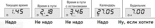
For quick adjustments, follow step 1 and step 2. If you then press button 1, the hours will be rounded up from 13:57 to 14:00. Or else: it was 14:05, but it will be 14:00.
Our editorial 2112 with BC Gamma GF 212. We are completely satisfied with it
The most popular non-standard ammo on the VAZ-2110 is the Gamma GF 212 model.
Its cost about 2500 rubles ... Installation is simple, you just need to connect to the K-line in diagnostic connector and connect the power wires.
There are such useful functions as candle blowing and more. We can only recommend it from ourselves among the large variety of models on the market.
MK 2114-3857010 turned up very well for 300 rubles 😉
Since I have long wanted to put a bortovik, but the prices for it, to put it mildly, bite - I took it without hesitation! 😊
The Router shows all the basic functions you need.
The backlighting of the display and the button labels is made in the traditional VAZovsklm style - green and yellow. When you press the buttons, the MK starts to make sounds ... bueeee ... 😥
Since the old owner was not particularly talkative and did not really explain what was happening in this MK, I began to look for instructions for this miracle of technology. The funny thing is that she's not on the drive. There are records about how someone bought and installed the same MK, etc., but not instructions.
After I reset the MK after the old owner, I more or less figured out the functionality:
MK is reset to zero by parsing and removing the battery
At the first connection to the power supply, MK welcomes by playing midi melodies - a la the old Nokia-brick.))))
So the buttons are from left to right:
1 T button
1.1. Travel time without stops. Counts howling while MK is on. You can reset to zero by long pressing start,
1.2. Total travel time for all trips
IF YOU SHORT PRESS START, you can set the brightness of the backlight using the plus and minus keys. Choose a value from 0 to 100%
2. KM / H button
2.1. Average travel speed
Pressing start in this menu turns off the notification. (I haven't figured out what kind of notification yet)
2.2. All-time average speed
If you click on START in menu 2.2, you can set yourself a speed limit, for example, at 120 km, the MK will start squealing
3. KM button
3.1. Trip kilometers
3.2. How many kilometers can you drive to the next gas station
4. L button
4.1. The number of liters in the tank - after zeroing, is not active yet. Most likely it will display how many liters were filled for the entire time
4.2. Fuel consumed since last refueling
5. L / 100 button
5.1. Fuel consumption per 100 km
7. H button
7.1. Clock. Exhibited by pressing start, then plus or minus
7.2. Date and month. Exhibited in the same way as the clock
7.3. Alarm clock. It is put in the same way
There are plans to make overexposure from green-yellow to white or red with an inverted screen.
To overexpose this MK will seem to be problematic, since removing the display is a whole story

A computer is today an everyday device that a large number of people encounter both at home and in a large number Vehicle. Speaking more specifically about car drivers, a computer, or as it is more commonly called, an on-board computer has become indispensable for each of them, because only with its help it is possible to take control of the operation of most units.
Video about the work of a non-standard BC on a VAZ-2114:
If we talk about cars made in Russia, then the firstborn in the AvtoVAZ family was the VAZ-2114, on which an on-board computer was mounted directly from the factory, which was able to notify the driver about all the events that were taking place, both outside and inside the car. Below in this article, we will analyze in detail what an on-board computer is needed for, and also analyze a brief instruction for it.
Reasons for installing the BC in the car

Established place in the instrument panel for the on-board computer. There is a plug on the photo.
The on-board computer of the first version, installed on the VAZ-2114, although it had few functions, nevertheless easily followed the main parameters of the car:
- Fuel level control , and its calculation of the number of kilometers traveled - this function allows the driver to make a decision in advance about refueling.
- Coolant temperature control - this function excludes engine overheating due to timely informing the driver.
- Diagnostics individual nodes car - allows with maximum accuracy, and most importantly mobility, to detect and eliminate the problems that have arisen.
More about on-board computer functions
On-board computers on the VAZ-2114 are able to display the following information on their working screen:
- Instantaneous indicators of engine operation, engine speed, temperature, real and average fuel consumption.
- Information about the car's mileage, travel time.
- The ability to accurately read the errors that have occurred in the system, which will allow you to immediately determine whether it is worth contacting a car service with a malfunction or whether it is possible to fix everything with your own hands.
Modern on-board computers, by type Multitronics - C340 and its analogs are also able to:
- Monitor and inform the driver in advance about the following technical inspection, car insurance, thereby performing the function of an organizer.
- To independently change the parameters for turning on the fan, change the notifications about a sufficient temperature for warming up the motor.
- It is possible to connect parking sensors.
Please note that in order to activate other advanced functions located in your bookmaker, its firmware may be required.
The principle of operation of the BC on the VAZ-2114

Not a standard on-board computer
The principle of operation of the on-board computer at first glance will seem primitive, however, in fact, it is a technically complex device that simultaneously receives, processes and, if necessary, notifies about the presence of malfunctions. The notification function occurs by displaying a special icon on the screen and giving a certain sound signal.
Brief user manual
For all on-board computers supplied to the VAZ-2114, there is a user manual, and if it is not in a paper version, then on the Internet it can be found without difficulty, it is enough just to know the brand and model of the device. Despite the fact that there are many options and models, their basic functionality is basically the same.

On-board computer readings.
- If you are just going to purchase a BC, then you should know if a particular model is suitable for your car's ECU. As a rule, the seller already has all the information, and there should not be any difficulties in this.
- It is better, first of all, when familiarizing yourself with the on-board computer, to devote time to the symbols of emergency commands and visual icons that appear on the display.
- Pay attention to the location of the buttons, and the rules for working with them, in order to quickly respond to changes in parameters in motion (on some BC models, the keys can be blocked at a certain vehicle speed - approx.).
Error codes for VAZ-2114
Since the ECU on all VAZ-2114 is similar or, at least, similar, it makes no sense to pre-record, let alone memorize them, since some models are able not only to display it on the screen, but also to voice all the problems in the car ...
The best option for identifying and clarifying faults will be a printed version of the error codes on the VAZ-2114. You can take them on the official websites of the manufacturers of BC for the VAZ-2114, and below we will present to you the most common mistakes that occur on the "fourteenth":
Codes Description 0102, 0103 Incorrect signal level of the indicator of control of mass air flow. 0112, 0113 Incorrect intake air temperature indicator signal - element must be replaced. 0115 - 0118 Wrong signal of the coolant temperature measuring element - sensor replacement is required. 0122, 0123 Interference or incorrect signal from the throttle position control indicator - it is advisable to replace the element. 0300 The on-board computer (BC) detected random or multiple misfires - in this case, the car may not start immediately. 0201 - 0204 An open circuit is detected in the injector control circuit. 0325 An open circuit in the detonation device circuit was detected by the on-board computer. 0327, 0328 Breakdown in the operation of the knock sensor - the device must be replaced. 0480 The cooling fan is out of order - you need to replace the element. 0505 - 0507 There are malfunctions in the functioning of the regulator idle movethat affect the number of revolutions (lower or higher). If this code occurs, the regulators must be replaced. 0615 - 0617 During the diagnostics, open or short circuits were detected in the starter relay circuit. 230 This error code means a breakdown of the fuel pump relay - the device must be replaced as soon as possible. 1602 It is one of the most common codes when diagnosing a BC for malfunctions. Means the loss of voltage of the on-board network on electronic unit management.
What to do if the bookmaker stops working
It happens that the bookmaker stops working or the information that it should transmit and analyze is not transmitted. First of all, you need to pay attention to the integrity of the electrical circuit. Namely, the fuse F3, which is responsible for its performance, then you should check the integrity of the wires that go to the diagnostic block and provide it with power. You can learn how to properly connect the on-board computer to the VAZ-2114 system in this article.
It makes no sense to describe the process of repairing the on-board computer itself, because such devices do not break often and are not easily repairable, therefore they have technically complex mechanisms inside themselves that require professional tools and skills.
To begin with, it is not so difficult to install an on-board computer in a regular place on a VAZ 2114 and other Samar models. In the installation of an on-board computer, in principle, there is no hassle with wires and nuts (unless, of course, no one has tried and changed anything in the car before you). A knowledgeable person will install an on-board computer for you in just 2 minutes, so you should not be afraid, hands in feet and forward with a song \u003d).
Why do you need an on-board computer?
In previous articles, we have already said what an on-board computer is, what it is for and what types they are. But let me repeat myself so that you are clearly aware of all the advantages of having an on-board computer, and the disadvantages - perhaps they are not, except that spending money on a purchase and that's it.
Take, for example, the STATE 115x24 on-board computer. Having this model in your stock, you can:
- set the temperature for starting the radiator fan; This function is very useful, for example, in the winter period, when you can control the temperature of the coolant, thereby monitoring the temperature of the heater radiator.
- the function of drying and warming up the spark plugs before starting the engine is very useful.
- the function of resetting the settings and adjustments of the ECU is needed to switch to gasoline with a higher or lower octane number (from 92 to 95 and vice versa), this function is also needed to reset the settings after a long trip with increased engine load.
- the ability to read errors allows you to monitor the condition of the car, change non-working sensors and elements in time.
On-board computer installation instructions
In this article we will look at the process of installing the Prestige on-board computer with the function of diagnosing and reading errors.
For work we need:
- Screwdrivers,
- on-board computer,
- wire 1m long.
We remove the plug on the central torpedo and look for a 9-pin connector in it. This block must be present on all cars of our model. It remains only to connect the block to the computer and that's it, but we need to draw a K-line.
How to draw a K-line?

- We take our wire and install it in the second contact of our block.
- We throw the opposite end of the wire under the dashboard down to the diagnostic block (for convenience, you can unscrew the right side panel).
- Having stretched the wire to the diagnostic block, we connect it to the "M" socket if you have a EURO-2 block or to the 7th socket if you have a EURO-3 block (it is very common that the diagnostic block for Euro-3 is installed on the car upwards feet, consider this)
- Now we connect the on-board computer, insert it into its original place and check it.
For a more complete and visual representation of the work, a diagram is presented.
What to do if there is no on-board computer pad under the dashboard?
In this case, it remains only to assemble a new block: buy a 9-pin block and lead wires to it according to the following scheme:

- fuel consumption signal (green wire)
- ignition (orange wire)
- + 12 volts (red / white wire) red wire with white stripe
- mass (black)
- speed sensor (brown wire)
- 6k-line (most often gray or black wire)
- mute (green / red wire) green wire with red stripe
- backlight (white wire, or you can take it from the size button)
- fuel level sensor (pink)
Errors when connecting / operating the on-board computer
Error: "There is no connection with the controller" or "K-line break".
This error indicates that the K-line is not connected or that the contact has been broken. Check the wire according to the diagram described above. Most likely, the contact from the diagnostic pads took off.
Error: Incorrect outboard temperature sensor reading.
If your temperature overboard is -40, then this indicates that there was a wire breakage to the temperature sensor, or there is no such sensor at all. If the temperature is, for example, -25, but outside it is only -10, then you need to replace the sensor with a working one.
You will also be interested in:

If you try to find out the weight of your car, you will realize that there are several ...

Begins in the early 60s with the launch of the 901 model. Since back in the 20s of the XX ...
Chevrolet Aveo's ground clearance or clearance, as for any other passenger car ...

As you know, the purpose of the power steering, be it electric or hydraulic, ...

