


Outwardly, it is easy to distinguish it from its predecessor by a different front end design, other turn signals and side lights. But the main family features have been preserved - "ears" - air intakes and stylish round lanterns. True, the air intakes on the 968 start at the rear axle, while on the 966 they were longer and started in line with the rear arch. The decorative "whalebone" grille disappeared from the front end, which gave way to a decorative chrome element.
Whoever said anything, but from the point of view of design, Zaporozhets came out very nice and harmonious. Many believe that its appearance was completely "lapped" from the NSU Prinz 1961. However, this is not the case - the first running prototypes appeared simultaneously with NSU - in the same 1961. But there is no doubt that the creators of both cars were inspired by the American Chevrolet Corvair.
Salon Zaporozhets is quite austere. The minimum instrument cluster is a speedometer and a fuel gauge. The arrow of the latter, when moving, dashes like the tail of a loving dog, and it is difficult to understand the true level of gasoline.
The salon is not only simple, but also cramped. Getting to the back sofa through the reclining chair and narrow door isn't easy. And it is not very comfortable to sit there.
The specific layout reminds the driver of itself. The front arches protrude strongly into the interior, which is why the pedal assembly is noticeably displaced to the right relative to the steering column. The choke lever is located between the front seats and the heater control is to the right of the steering column. But the gear lever is right at hand.
The rear-engined layout has resulted in the trunk being at the front. Moreover, this is even stated in the native operating instructions. So the Zaporozhets has a "front trunk and tailgate". The luggage compartment is very small. An already small volume is eaten up by the spare wheel, battery and gasoline stove.
Another task for an unprepared person can be refueling at a gas station. After all, the neck of the fuel tank cannot be found outside - it is hidden under the hood. And the hood opening handle is located on the B-pillar.
Warm heart
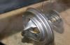
The air-cooled MeMZ-968 1.2-liter engine develops 41 hp. at 4200 rpm. It is very simple and maintainable, and so lightweight that two people are enough to dismantle it.
The power system used a K-126 carburetor and an inertial air filter that did not require replaceable filter elements. Unfortunately, the Melitopol airplane was not particularly reliable. These engines rarely nursed 100 thousand km - often half as much. The engine suffered from overheating, as did the gas pump, which in some situations could simply stop pumping fuel. But what you definitely can't deny this motor is in. Fuel consumption was kept around 6 l / 100 km at 80 km / h. It's a paradox, but the next iteration of the Zaporozhets - 968M, popularly nicknamed "soap dish", spent much more - about 10 liters per hundred at the same 80 km / h.
There is no need to talk about any dynamics. In theory, Zaporozhets reaches 100 km / h in 32 seconds. And the maximum speed is 118 km / h. But in practice, at 80 km / h, any acceleration has already stopped. And there is no desire to go faster on 968.
Soft move
The suspension is completely independent - torsion bar in front, spring in the back. And the ZAZ 968A also has a perfectly flat bottom and a large ground clearance of 200 mm. All this endowed the Zaporozhets with decent cross-country ability, which the other passenger cars of the USSR would envy.
The wheels of the Zaporozhets are diskless, and the hubs are brake drums. And the brakes are one of the weak points. The deceleration is sluggish, the drive is uninformative even by the standards of the 70s. Therefore, it is better to slow down on 968 in advance. But he has a very good ride. What can not be said about handling: with an increase in speed, the car starts to wag, and after 80 km / h, driving it is frankly scary.
But at the same time, Zaporozhets has a very light steering wheel, which can be twisted without unnecessary effort even while standing still. In addition, the front wheels turn at a very large angle. And this, together with its small size, gives the "eared" excellent maneuverability.
The car is very noisy. And everything is noisy - the wind is walking in the doors and windows. The engine rumbles recognizably. The transmission howls. And after 70 km / h a very characteristic and incredibly funny whistle of those "ears" is added. The noise level is another reason why it makes no sense to go faster than 80 km / h.
Despite all its shortcomings, Zaporozhets was loved. For his naive look. For incredible simplicity and maintainability. And for a small cost - the car at the time of its appearance cost only 3,500 rubles. For comparison, it cost 5500, and the VAZ "treshka" - all 7500. Therefore, he often became the first car in families who could not afford more. And the Zaporozhets performed its transport function successfully, regardless of the quality of the roads.
Photo: Christina Traktirova
MAIN TRANSMISSION
It is possible to remove the axle shafts only by draining the oil from the main gear case, since the oil level is higher than the edge of the hole covered by the axle shaft cover. Then, after removing the cover and disconnecting the flange from the cardan joint, we take out the axle shaft from the axle shaft gear. In this case, it is necessary to rotate the semiaxis so that her the finger has taken a horizontal position to avoid the falling of the crackers.
The semiaxis must be installed with its horizontal position - otherwise the cover will warp, and its collar will not evenly fall into place. If it is not possible to use the overpass or pit, you can raise one side of the car, remove the wheel, put some support under the brake drum and lower the car to a position where the axle shaft fixed at the ends will stand parallel to the bottom of the car.
We have made sure more than once that there is no need to rush to install the cover. After all, if a leak is revealed, then the cover will have to be corrected with the following of oil.
Leaks can occur due to insufficient tightness of the cover, which presses the cover flange. Sometimes it is enough just to tighten three nuts, but if the cover has reached the stop, and there is no normal clamping, it is necessary to put a ring with an outer diameter of 128 under the cover of the appropriate thickness mm and internal 108 mm or lay a ring of wire insulated "with a diameter of 1.5-2 mm.
It is better to replace damaged covers with new ones. If not, then you can repair old ones with patches or a plastic bag inserted into the cover.
Changing the cover, according to the operating manual, is done after removing the flange from the axle shaft. However, it is not always possible to remove it with "light hammer blows". Most often, this will require pouring kerosene into the joint of the flange with the axle shaft and holding it for several hours. If this does not help, heat the flange with a blowtorch.
There is another way to remove the cover. Place the axle shaft vertically, step on the flange with your feet and pull the cover upwards using the collars. When the cover is released from the oil seal housing, it will quietly pass through the axle pins. Naturally, if the oil seal body is glued (in cars produced after the II quarter of 1975), the glue must first be dissolved in acetone.
However, there are times when the splined connection of the half-shaft with the flange is loose. This manifests itself in knocking when the vehicle is moving. Car enthusiasts use several methods to restore the immobility of the connection. The most effective way is to glue the joint with epoxy glue and add steel filings to it. The glue is applied to the surfaces of both parts and, after assembly, is kept for a day. When disassembling the connection
a blowtorch is required.
The dirt deflector, which has been installed on Zaporozhets since the beginning of 1982, very effectively protects the oil seal of the cover. We highly recommend installing it on the axle shafts of older cars. If it is possible to purchase a dirt deflector (part number 968M-2403094), it is installed on the semiaxis so that the distance from the end of the semiaxis (from the side of the finger) to the outer edge of the dirt deflector is the factory recommended value 199 + - 2 mm.
If you couldn't get a regular dirt deflector, you can use the advice of experienced ones and buy a plunger (a rubber cap used to clean drains in sinks and bathtubs) at a hardware store. A hole is made in the plunger to put it on the axle shaft with an interference fit. The edges of the plunger cup should overlap the protruding part of the axle shaft protective cover.
Dismantling and assembling the universal joint in stationary conditions is not very difficult. We have made sure that this work can be carried out successfully in the field as well (perhaps the hopelessness of the situation pushes here).
We stopped on a lost country road after it became unbearable to hear the knocking around the rear wheels. The reason was quickly discovered: when the wheel was standing, the axle shaft flange turned 90 degrees. Having removed the cardan joint, they found that the bearing housing had crumbled and all the needles fell out of it. We had the crosspiece and bearings with us.
Instead of a workbench, a tripod came very well, which we always carry with us to support the raised side of the car. This time we did not use the tripod for its intended purpose, since the cardan assembly can be pulled out of the rear wheel hub without lifting the car. It turned out that the hinge body just goes into the hole in the tripod for the support rod. Putting a fork on the surface of the tripod, they began to knock with a hammer on the end of the opposite bearing through the head of the socket wrench. Everything moved perfectly to one side. Naturally, all locking half-rings were previously removed. The rest was a matter of technique.
The only thing is, do not forget to lubricate the bearings during repairs. To do this, you can use the channels of the cross, into which you consistently pour oil before installing it in the bearing.
Zaz 968. FRONT SUSPENSION
The most common work associated with partial disassembly of the suspension is replacing the shock absorber or its rubber bushings, replacing the steering knuckle liners, torsion bars and shock absorber springs.
When changing the shock absorber, it is required to hang out the front wheel (for a better approach, you can remove the wheel), loosen the nut of the upper shock absorber mounting, unpin and unscrew with a wrench 24 mm ball stud nut. Grasping the bottom of the shock absorber, turn it so that the ear comes out of the finger. In this position, the bushings can be changed. On some cars, it is not possible to remove the shock absorber ear from the finger due toa short distance from it to the wall of the mudguard. In such cases, you can get by with a minimum of additional work: unscrew the nut (clamping the suspension arm, remove its screw and, hitting with a hammer from the inside on the top of the fist, move the finger relative to the lever.
Changing the knuckle ball joint liners will require more detailed disassembly. Here you need to sleep the drum, pads, brake shield, unscrew the screw plugs of the knuckle joints. If you only need to replace the outer ball pin bushing, you do not need to disconnect it from the lever.
Dismantling the steering knuckle begins with removing the wheel, then disconnect the side link, the shock absorber (lower part) from the steering knuckle, and release the screws of the levers terminal clamp. By blows of a heavy hammer on the fist, the fist with fingers is advanced from the clamps of the levers. In the end, you need to make sure that your fist does not hang on the brake hose. After releasing the fist, it can be temporarily suspended by a finger with a screwed on nut, inserting it into the ear of the shock absorber.
The suspension arm is secured against axial movement by a bolt entering the torsion hole. Therefore, first of all, it is necessary, by unscrewing the lock nut, to unscrew the locking bolt with a special hex key 8X17 mm. Sometimes the bolt is so "caught" that its internal hex is broken. In such cases, the bolt is unscrewed by the outer surface with a gas wrench.
When the lever is pulled out of the tube, the end of the torsion bar is exposed. If the torsion bar needs to be changed, then it is also necessary to release the lever on the opposite side and unscrew the middle center bolt of the pipe. When removing the torsion bar from the pipe, oil will pour out, therefore, a drain can must be placed under the ends of the pipes.
Usually, the torsion bar is taken out by the end with pliers. But there are cases, especially in the absence of lubrication or breakage of the torsion bar, when it is very difficult to remove the torsion bar. It is necessary to try to knock on one side and the other, and then knock out the torsion bar through the drift in a more pliable direction. The installation of the torsion bar begins by pulling it through the square hole of the middle support. Then you need to screw in the locking bolt until it stops and knock on the end of the torsion bar so that the bolt falls into the hole. After screwing in the locking bolt again as far as it will go, tap on the opposite end of the torsion bar and tighten the bolt completely. Further assembly is straightforward.
After disassembling the ball joints or removing the suspension arms, the camber and toe of the front wheels must be adjusted. Camber is easily checked by plumb line. The distance from the plumb line to the upper and lower edges of the wheel rim is measured. The difference should be within 1-5 mm.
If the camber value does not fit within the norm, it is necessary to make a correction by rotating the ball pins with the screws of the terminal clamps loosened. The upper pin is rotated with the same wrench as for the torsion bar locking bolts. First, it is necessary to loosen the fastening nut on the shock absorber pin.
The lower finger is turned with a key 12 mm for flats. It should be remembered that the finger extends outward when we rotate it counterclockwise (as viewed from the mudguard).
However, there are often cases when wheel camber needs to be increased, but there are no opportunities for this. In other words, the adjusting fingers are in the extreme position in the levers. This, by the way, is the most common excuse for kicking you out of a service station if you decide to make a "collapse" there.
What is the reason for the impossibility to establish the necessary collapse? The first is the deformation of the suspension arms. It is determined with the steering knuckle removed by measuring the distance between the ends of the upper and lower levers. The lower lever should protrude beyond the level of the upper one by 10 ± 2 mm. The second reason is the wear of the steering knuckle joints and, first of all, the inner ball surface of the pin and the inner liner. With equal wear of the upper and lower joints, camber should not change. It decreases with more wear on the lower hinge. It is especially bad when, in the absence of lubrication, the inner liner collapses and the surfaces of the pin and the housing of the inner part of the steering knuckle are exposed to intense wear.
Therefore, the installation of new earbuds, as many do, may not give an effective result without replacing the fingers themselves. In case of significant wear on the inner surface of the knuckle, you may have to change it. When changing the inner liners, the seat must be thoroughly cleaned, since the remnants of the old liner are often mistaken for the surface of the fist.
But what if the collapse still cannot be brought back to normal? The first way is to lengthen the screw groove of the fingers with a file. Sometimes it is enough to do this on the upper finger, sometimes also on the lower one. And only as a last resort, you should drill a new hole in the torsion bar.
And one more tip: if you can't deal with negative camber on one wheel, then at least reduce camber on the other.
We measure the toe-in with a store-bought rail with a spring-loaded end and a scale that we insert between the wheels at the front and rear. Thanks to two plumb lines on the edges of the 180 mmensure that the rack is perpendicular to the wheels and the same level from the ground. The difference between the rear and front wheels must be within 1-3 mm. If necessary, adjust the convergence by rotating the transverse link.
Naturally, the operations to measure the camber and toe should be carried out on a flat, horizontal section.
During maintenance of the ZAZ-968M front suspension, care should be taken when tightening the filler plugs
torsion tubes. It costs nothing to tear the threads in the pipes, since
her very little in the cylindrical wall.
Zaz 968. REAR SUSPENSION
Removing the rear suspension from the vehicle is easy. The suspension arm is supported by two silent block bolts and the lower end of the shock absorber. But the rear brake drive line and the parking brake cable are suitable for the lever, which must be disconnected.
We remove the end of the parking brake cable from the finger of the expanding lever (unpin the finger) on the brake shield, and remove the cable sheath from the slot of the stop wall, having previously unbent the locking plate.
The tube coming from the working brake cylinder is disconnected from the hose, releasing the union nut at the same persistent walls parking brake cable sheath. Naturally, disconnecting the pipeline will then require bleeding the brake system to remove air.
Is it possible to do without this operation? There is a way to avoid disconnecting the pipeline if, when removing the suspension arm, take off Hang the bearing housing and brake shield from the piping. And to disconnect the pipeline from the lever, in a persistent wall cut a groove with a hacksaw, similar to the groove for the cable parking brakes. So that the pipeline does not jump out of groove, it can be tied to the stop wall with a wire.
When removing the bolts of the silent blocks, it should be borne in mind that the extreme bolt cannot be pulled out of the bracket, since its head is located next to the side wall of the bottom at the threshold. Therefore, it is necessary to detach the lever together with the bracket. Key 17 mm unscrew the 2 bolts outside and the nut under the rear seat.
Often, especially when the car is operated in winter, it is difficult to remove the bearing housing from the lever hole. They grow together tightly due to the rust formed from the action of salt, which is sprinkled on a winter road.
There is no need to rush here in order not to irrevocably damage the parts. First you need to swing the body with hammer blows through the hammer. Strikes should be applied alternately on the right and left
body flange protrusions. When the hull starts to move
and will turn a little (at least from blows), we drive a large screwdriver into the joint between the body and the brake shield. Then, by striking the body from the inside (through the hole in the lever), we finally knock out the body. Before installation, it is necessary to remove rust from the surface with lithol.
After suspension assembly, and sometimes just as operation requires adjustment of the position of the rear wheels. To carry out this operation is forced by the beginning intensive wear of the rear wheel tire.
Let us recall the method for controlling the toe-in of the rear wheels. Each wheel is adjusted separately by driving a spacer under the vertical shelf of the bracket: inner - to increase toe-in and outer - to reduce. The gasket is made of steel strip 60X30X1 mm, in which a groove is cut with a depth of 22 mm for M12 bolt. One such spacer gives a change in toe (the difference in distances from the vehicle axis to the front and rear points of the wheel tire protrusion) 0.5 mm.
Since the axis of the car is difficult to determine, it is replaced by a parallel transfer to the outside of the car of the tensioned thread touching the sidewall of the front wheel and through the spacer - the rear. The spacer must have a thickness equal to half the difference between the front and rear wheel tracks. Then measure the distance between the thread and the front of the rear wheel sidewall. Convergence is considered normal if the measured distance differs from the thickness of the spacer by ± 2 mm.
As for the camber of the rear wheels, it must be installed by itself with correct assembly and compliance with all the details to the drawings. However, during operation, the camber can change under the influence of deformation of the lever and the supporting surface of the body, as a rule, towards the negative side.
According to our observations and the results of comparing data on the rear-wheel drive vehicles previously produced abroad, the camber of the rear wheels should be 0 ° ± 1 °. Based on this, the difference between the distance to the plumb line from the upper to the lower edge of the wheel rim is ± 5 mm can be considered the norm. Provided that such a difference between the left and right wheels does not exceed 2.5 mm.
What to do if the collapse is more than normal? Small compensation up to 2 mm can be achieved by placing spacers under the horizontal shelf of the arm bracket. In this case, it may be necessary to slightly saw the holes in the body for the horizontal hinge bolt. If you need to remove a larger camber, you will either have to change the lever, or make its hinge. We had a case when the negative camber was 14 mm, and after changing the lever - 3 mm.
Zaz 968. STEERING
Most often in steering it is necessary to disassemble the steering rod joints.
Having untwisted and unscrewed the nuts of the fingers, it is necessary to remove them from the tapered holes of the rods. Usually, the taper of the pin to the hole is so tight that you cannot pull the pin out without effort. The fastest unpressing is applying sharp blows with a hammer to the side surface of the part where the finger is pressed.
However, in order for the finger to fall out from the blows, a certain Skill is needed, and at first this may not work. Then it is necessary to use devices.
There are no devices for pressing the fingers of the Zaporozhtsev on sale, but there are for Moskvich. This is a cylinder with a sheared side surface, which has a recess on one end and a screw on the other. The device is inserted with a recess in the gap between the rod and the hinge; the screw is brought to the end of the finger and, when rotated with a key, squeezes it out.
With such a device, the fingers of the "Zaporozhets" are normally un-pressed, except for the middle fingers of the steering arm and the pendulum arm, where the device is not included.
You can press out the finger using a clamp, after removing the plug from the hinge. In this case, from pressing the screw on the end of the finger, the latter falls through two adjacent parts at once. To remove the hinge cap, you need to release the retaining ring. It is constantly pressed by the hinge spring to the end of the groove, thereforeFigure: fifteen. Removing the locking ring of the ball pin 1 - steering rod, 2 - puller, 3 - ball finger, 4 - locking ring, 5 - press the round-nose pliers on the plug.
This is easily done with a small universal puller (fig. 15). Its paws need to catch on the body
hinge (after lifting the protective cover), and press the screw on the center of the plug. As soon as the interference has disappeared, we squeeze the antenna of the locking ring with round-nose pliers and remove it from the groove. We release the puller and remove the plug, seal, spring, thrust washer and insert from the hinge.
After disassembling the hinge, the locking ring often loses its elasticity and, when installed in place, pops out of the groove. It is not possible to completely restore elasticity, but the outer diameter of the ring can be increased. To do this, put the ring on a smooth metal support and knock on it with a hammer. The ring will flatten a little and expand in breadth.
Having finished assembling the hinge, do not forget to coat it with plasticine from the side of the plug.
We've talked a lot about how difficult it is to depress the ball pin. But when not necessary, it can be uncompressing itself, and then it is required to tighten it. This is not always easy to do because the finger can rotate with the nut, and there is nothing to support it.
In this case, we screw the second nut М10Х1 onto our finger, and inside this nut we tighten the screw with effort. Supporting the additional nut with a wrench, it is easy to tighten the main nut. If you do not have a nut and screw M10X1, then you can temporarily borrow the shock absorber mounting nut (in the trunk or engine compartment), and the screw from the axle shaft flange.
Loosening of the steering mechanism "Zaporozhets" is a fairly common phenomenon. Therefore, it can hardly be considered justified to unscrew the main fixing screw from the side of the mudguard to control the oil level in the steering gear.
In general, it is better not to touch this screw, as the thread in the aluminum steering box is very weak. But, on the other hand, it must be tightened as it weakened. There is a way out of this situation - to replace the standard screw M10X55 with a longer one with an additional nut. Such a screw is screwed all the way into the body of the steering mechanism body, and the tightening to the mudguard is carried out with a nut when the screw is stationary (Fig. 16).
When it comes to controlling the oil in the steering gear, it’s better to just add oil from time to time through the plug in the gear cover.
 Figure: sixteen. Steering gear attachment:
/ - steering gear, 1 - screw, 3 - nut, 4 - spring washer, 5 - washer, 6 - adjusting washers
BRAKES
The main difficulty in disassembling the main brake cylinder is disconnecting it from the pipelines. Sometimes it only takes a minute, more often it turns into a problem.
Usually the wrench crushes the edges of the nuts and turns. The first rule is to use a relatively new key,the mouth of which more tightly covers the nut. But even that doesn't always help.
Figure: 17. Elimination of brake fluid leak from the pipeline seal: / - cylinder union, 2 - tube, 3 - nut, 4 - lead gasket

Car enthusiasts have come up with a whole arsenal of various devices for loosening pipe union nuts. These are special clamps, improved pliers, special nuts, etc. We, for example, use a special nut, which is easy to make at home from a standard M12 nut. We give the hole of the nut with a file a hexagonal shape so that a nut with a wrench size 12 fits tightly into it mm. Then, on one face with a hacksaw, we make two through cuts to form a groove 6 mm.
We put such a special nut through the groove on the pipeline, and then on the pipeline nut, and with a key 19 mm calmly unscrew the nut.
Well, if there are no accessories, and a regular wrench is already turning along the edges of the nut, you can use a gas wrench. However, it is better to spend the extra half hour to make a special nut, since after using a gas wrench, the surface of the pipeline nut will deteriorate even more.
Leakage may occur after piping is connected to the cylinder due to damage to the inner surface of the flared tube. To ensure a seal, we use a lead cap made from a pre-flattened strip of lead. The cap itself is formed from a strip placed on a plate with a hole by lightly hitting a rod (for example, a screw), which deepens the strip into the hole in the plate. A hole is made in the center of the cap. The cap is placed on the spherical protrusion in the cylinder bore, which will now go into the inside of the tube through the lead gasket (Fig. 17).
To remove the pistons, it is necessary to unscrew the two stop screws from the bottom of the cylinder. Regardless of the condition of the cuffs, it is better to change them.
When disassembling the brake master cylinder, unscrewing the end nut causes a certain difficulty, especially when there is no powerful vise in which to clamp the cylinder. We use this technique. We cover the cylinder body at the nut with an adjustable wrench, and put a socket wrench with a head 27 on the nut mm, the handle of which is extended with a pipe. We put the cylinder with the keys on the floor. We hold the adjustable wrench with one foot, and press the end wrench with the other (Fig. 18). With such a powerful attack, the nut always gives in.
It is necessary to assemble the cylinder from the side opposite to the threaded part so that the cuffs do not wrap when passing the thread. First, we lower the piston of the rear wheels with a cuff and a washer at its end into a vertically placed cylinder, and tighten the limiting screw. Then we put a large-diameter spring, a cup, a small-diameter spring on the second piston, insert everything into the cylinder, fix it with a limiting screw.
Sometimes it is necessary to re-fix the plastic connection of the fluid supply to the cylinder. This is due to a loosening of the lock washer or due to its breakage. Once, for this reason, we completely drained the liquid from the tank.
Before installing the fitting, it is necessary to thoroughly clean the seat and especially the groove into which the teeth of the lock washer should jump.
We put a rubber sealing ring on the fitting on the lower side, a lock washer on the upper side and lower the entire
 Figure: 18. Unscrewing the end nut of the master brake cylinder
set in the cylinder socket. Then we put a tube or a suitable socket wrench head on the fitting and hit it with a hammer. The fitting will sit in place, and the lock washer will lock it in the socket.
However, there is a case when after this the brake fluid again appears. Here the matter is in the O-ring, which, apparently, does not have enough effort to press firmly against the surfaces of the cylinder and the fitting. You can correct the defect by placing a homemade washer cut from copper foil or tin under the spring washer.
Worse when the lock washer is broken and there is no spare. In this case, a clamp can be made of sheet metal around the cylinder so that it presses the fitting through the pipe section.
It is necessary to disassemble the brake slave cylinder when the cylinder leaks. Before disassembling, seal the hole on the reservoir cap with adhesive tape, then the brake fluid will not leak out so much.
Disassembly is simple: remove the protective cylinder cover and unscrew the piston with a screwdriver. Then you need to inspect and feel the working surface of the cylinder. If it has scratches or a lot of wear, then you need to change the cylinder assembly. If the condition is normal, then it is enough to change the cuff on the piston. Recall that on the upper cylinders of the front wheels and on the rear wheels, cuffs with a diameter of 19 mm, on the lower cylinders of the front wheels - 22 mm.
It is convenient to put on the cover of the working cylinder straightened, and then unscrew the edges of the cover on the cylinder.
To remove the brake pads, you need to free them from the tie- others springs. The springs on the front brakes are the same, on the rear ones they are different - the upper one is longer than the lower one. Use a large screwdriver to pry on the end of the spring and "shoot" it.
The springs are easy to install. One end is inserted into the hole of the shoe. The second end is put on some kind of tapered rod, for example, the non-working part of the file. The thin end of the rod is inserted into the hole and the other end is pulled back until the spring catch is behind the hole. In this case, the hook begins to slide down the rod and falls into the hole (Fig. 19).
Some difficulties sometimes arise when putting on a brake drum on new pads, especially on restored ones with glued linings.
|
|

Figure: nineteen. Installing the tension spring to the boats
The first obstacle is that the drum does not fit on the pads at all. There may be three reasons for this: the collar is on the brake drum, the pistons are not in the extreme position, the pads on the pads are too thick.
The collar on the brake drum can be easily cut with a triangular scraper or, if not available, a file.
The Zaporozhtsev brake cylinders automatically adjust the gaps between the pads and drums, but this adjustment is carried out in one direction as compensation for the gap that increases due to wear.
Therefore, when we install new pads, the split rings in the cylinders are in the old position, that is, they are shifted to the periphery by the amount of pad wear. To return the split rings to their original position, it is necessary to pull the pads from opposite sides with mounting blades, catching on the shoulder of the brake shield. In this case, it is imperative to slightly unscrew the cylinder valve so that when the fluid piston moves, you can go somewhere.
If the operations undertaken do not help, you will have to file the surface of the linings with a file. Locations of material removal are determined by turning the raised wheel with the engine or by a test drive.
Some motorists, in order to put on the drum, slightly cut off the ends of the pads, which rest against the piston slot. But this is not the best way. By cutting off the end of the pad, we break the shape of the cylindrical surface, which will lead to incomplete adhesion of the pads to the drum.
Operations for disassembling at least one cylinder end with bleeding the brake system to remove air. This is done by repeating the cycle - pressing the brake pedal 3-5 times, turning the valve half a turn.
The pumping operation in the absence of a trestle requires hanging the rear wheels in order to get to the valve of the working brake cylinder. The front wheels do not need to be hung, just turn them so that the valve is accessible. Usually, two people do the pumping: one at the wheel, the other in the cabin.
But there are ways to do it alone. The first method comes down to fixing the brake pedal in the depressed position, in which, after leaving the passenger compartment, you can unscrew and wrap the cylinder valve. The pedal can be secured with the tire pump against the front seat.
For the second method, you need to have a special tank lid with a valve. Air is pumped into the tank and thus pressure is created in the system.
It is rare to see a Zaporozhets with a parking brake that works well. When you adjust it for reliable braking, it continues to brake the wheels in the original position. If adjusted so that the pads do not touch the drums, there is not enough travel for braking.
This is due to the design features of the parking brake drive. The absence of a fixed hinge of the lever requires a large cable travel due to the sequential, and not simultaneous, as in other cars, movement of the pads to the drum. In addition, the supports of the cable sheaths are not rigid enough. Under these conditions, the effectiveness of the parking brake is so dependent on a slight change in the condition of the working surface of the pads, wear of the linings and other factors that many motorists do not use the parking brake at all. Well and it is not difficult to demonstrate good brake performance once during a technical inspection, since the traffic police do not check whether the brakes are fully released after applying the "parking brake."
How to fix the situation? You can think of several ways, however, you should remember the requirement of the traffic rules that you cannot operate a car with a modified design of brake systems provided by the manufacturer.
For example, without changing the design of the parking brake, we improved its efficiency by increasing the total travel of the brake lever. To do this, you need to disassemble the lever, saw off the upper part of the toothed sector (by 3 teeth), and cut a groove in the handle from the bottom so that the lever goes lower. The leveling roller must be moved forward to the second position.
Such an alteration on the ZAZ-968M also allows you to have a more rational position of the lever handle, which provides more effort and does not create inconvenience when driving (for undersized drivers, the elbow is peeled off against the constantly protruding lever handle).
Zaz 968. STARTER
To remove and install the starter, you must have access to the lower right side of the engine. The easiest way to do this is on an overpass. If this is not possible, you need to raise the right side of the car, place a stand under the rear suspension arm and remove the rear wheel. Then disconnect the battery. By removing the sunroof cover from the right side of the engine mudguard (unscrew 2 MB screws), you will gain access to the starter relay. To disconnect the wires suitable for the relay, you need Keys 12 and 8 mm. In order not to confuse the wires during installation, you need to remember or write down their location. However, those that fit the thick contact bolts (M8) have lugs with a large hole, so it is difficult to confuse them. We are talking about two wires: blue for the starter going to the additional relay and white for the ignition coil. When viewed from the end of the starter mounted on the engine, the blue wire must be connected to the bolt located to the left of the thick bolt. On the cover of the relay, the stud with a white wire has a mark (VK), but it is not always possible to see it in the dark under the car.
Having freed the starter from the wires, using the key 17 mm unscrew the two nuts located on the clutch housing flange, and remove the starter together with the studs through the mudguard hatch.
Starter malfunctions are most often associated with wear of the drive, brushes and burning of relay contacts.
To replace the actuator, unscrew the two cap screws 9 mm, disconnect the wire from the starter to the relay. Then, by inserting a screwdriver into the gap between the stator and the drive cover, we move the stator and remove it. To remove the rotor from the drive cover, uncouple and remove the lever pin.
Remove the starter drive from the shaft only after removing the locking ring.
To change the brushes, you must remove the stator and the back cover from it. In this case, two brushes connected to the stator come out of the plastic brush holders of the cover, while the other two, connected to the "mass", remain in the cover.
We had a case when a wire fell out of the brush. There was no new brush. We got out of the situation like this. An M4 thread was cut in the hole of the brush, the end of the wire was tinned, and the thread was also cut. The brush was wrapped around a wire and so we traveled for several years.
If you suspect a malfunction of the contacts of the starter traction relay, you must unscrew the nut of the M5 bolt (without marking "VK") and two screws securing the cover. Remove the cover carefully by pressing on the bolt, which, after removing the cover, will hold onto the relay coil wire.
The contact bolts are removed from the lid and cleaned on a plate wrapped in fine sandpaper. Sometimes, on the surface of the contact heads of the bolts, such indentations are formed that cannot be removed with a sandpaper. In this case, it is necessary to turn the bolts in the square holes - the sockets of the cover so that the contact disc is pressed against the un-worn surface.
It is not necessary to remove the entire starter from the vehicle to repair the starter relay. Only the relay housing can be removed by unscrewing the two screws on its flange. Before that, be sure to mark with a risk the relative position of the relay and the starter housing so as not to disturb the location of the relay contact bolts.
after adjusting the side play, put the stoppers 2 (see Fig. 87) of the adjusting nuts. It is allowed to slightly turn the nut until the mustache of the stopper and the slot coincide. In the absence of a device, the clearance in the meshing of the main gear can be checked with reliable accuracy by the angle of rotation of the nut 39 (see Fig. 84) of the driven shaft. The rotation angle of the nut, equal to 14 "... 37", approximately corresponds to the clearance in the engagement of 0.08 ... 0.22 mm;
put the shift rods in the neutral position, grease the place of the crankcase connector and the rear cover with UN-25 sealing paste, install the gasket, insert the slider rod into the hole in the rear cover and install the rear cover;
check the ease and clarity of the transmission. Lubricate the top cover gasket with UN-25 sealing paste on both sides and put the top cover on.
DESIGN FEATURES OF THE GEARBOX CONTROL MECHANISM
The gearbox is controlled by lever 1 (Fig. 97) on the body floor tunnel. The lower end of the lever is installed in a stamped body on a ball bearing. The ball part of the lever provides an articulated connection with the slider.
DIV_ADBLOCK291 "\u003e
The housing 28 of the mechanism is attached to the tunnel with four bolts 27 and is closed with a cover 7 with a rubber casing 3. The slider rod 21 is connected to the control shaft 9 by a setting bolt 8. The control shaft 9 is connected to the gearbox slider 13 by means of an elastic rubber coupling 16, which is screwed into control shaft 9 and is locked with a nut 11. The second end of the clutch 16 is connected to the gearbox slider 13 by a bolt 12.
An indispensable condition for a clear and easy engagement of all gears is a reliable tightening of the locking bolt 8, nut / 5, locknut II, as well as the location of the lever / control in a neutral position at an angle of 90 ° to the plane of the body floor tunnel.
REPAIR AND ADJUSTMENT OF THE GEARBOX CONTROL MECHANISM
Disassembly and assembly. To remove the gearbox control mechanism from the car, you must:
remove the cover 7 (see Fig. 97) with the rubber casing 3, having first unscrewed the handle of the lever 1 ", unscrew the four bolts 27 fastening the housing 28, move the mechanism housing forward as far as possible
To disassemble the gearbox control mechanism, unscrew two bolts 29 ", remove the spring 25 of the slide and the ring 24, remove the slide 21 from the support, remove the three bronze inserts 20, and then the rubber bushing 19, squeezing it to the center of the hole.
Collect this unit and install it on the car in reverse order. In this case, worn parts are replaced with new ones. Before assembly, the rubbing surfaces of the slider 21 of the cups 6, 22 and the liners 20 are lubricated with graphite grease.
Adjustment of the mechanism. The gearbox control mechanism is adjusted at the factory during assembly, however, during the operation of the vehicle, it may be necessary to remove and then adjust the mechanism.
For correct installation of the mechanism it is necessary (see Fig. 97): set the gearbox slider 13 to the neutral position, and the mechanism housing into the floor tunnel and connect the lever slider 21 and the control shaft 9 with the stop bolt 8,
screw the bolts 27 of fastening the mechanism to the tunnel, but do not tighten them, install the dust cover 18 in the hole of the tunnel plug and screw the coupling 16 into the control shaft 9 to a size of 13 mm between the end of the shaft and the plane of the coupling;
attach the second end of the clutch to the gearbox slider 13, tighten the nut / 5 until it stops, set the gear shift lever 1 to the position at which the reverse gear is engaged, but do not engage it;
turn the slider 13 of the gearbox with the clutch 16 to the position for engaging reverse (from the side of the control shaft, the slider should be turned counterclockwise) and in this position, holding the shaft with a key, tighten the lock nut 11;
check the position of the shift lever. The lever in neutral must be set at 90 ° to the plane of the body floor tunnel. The position of the lever is adjusted by moving the body of the mechanism along the longitudinal slots of the body and the tunnel.
After adjusting the position of the lever, the fastening bolts 27 should be tightened to failure, then check the clarity, ease and completeness of the gears (readjust if necessary), reinstall the cover and the dustproof rubber casing. Maintenance of the gearshift mechanism consists of periodically checking the position of the gearshift lever and tightening the connections. The mechanism is lubricated at the factory during assembly, however, during operation during disassembly, it is recommended to lubricate the rubbing parts with graphite grease.
HALF AXLE
CONSTRUCTION FEATURES OF SEMI-AXES
The car is equipped with fully unloaded axle shafts. At one end, they slide in the grooves of the semi-axle gears of the differential, and at the other end, they are connected to the hubs of the rear wheels through cardan joints. The sliding device of the semiaxis (Fig. 98) is made in the form of a finger pressed into the head of the semiaxis and two crackers put on the finger.
The universal joint is connected to the semi-axle with a splined joint and is locked with a pin 14. Cardan joint consists of two forks / 7 and 18, in the hole of the lugs of which the needle bearing housings of the crosspieces are pressed. The housings are secured on the inner side of the lugs with snap rings. Each of the four cardan joint bearings contains 20 needles with a diameter of 3 mm. The surfaces of trunnions, crosses and housings at the needle landing site are cemented and hardened.
Flanges "href \u003d" / text / category / flantci / "rel \u003d" bookmark "\u003e of the flange a dirt deflector is installed on the axle shaft.
SHAFT REPAIR
Removal and installation of axle shafts. To remove the axle shaft it is necessary to unscrew the bolts securing the differential protective cover to the final drive housing, then unscrew the bolts securing the axle shaft to the universal joint fork, move the axle shaft aside and remove it together with the cover. When disconnecting the axle shaft only from the universal joint fork, immediately push the axle shaft into the differential and tie it to the suspension arm, otherwise the crackers may come out of the grooves of the half-axle gears, which will lead to the cracks falling off the pin, breakage of the differential or the gearbox housing.
Install half shafts it is recommended in the following sequence: insert the semi-axle with breadcrumbs into the grooves of the differential semi-axle gear; bring the axle shaft flange fork to the universal joint yoke and tighten the four bolts with spring washers. The tightening torque of the bolts is 5.5 ... 6.0 kgf-m. Next, install the boot cover on the differential protective cover and tighten the nuts with washers.
Before installing the axle shaft, make sure that the circlip of the adjusting nut of the driven gear of the main drive is installed between the cover and the differential bearing housing, and also make sure that the right axle shaft is installed on the right side, the left on the left.
Dismantling the axle shaft and cardan joint. Dismantling the axle shaft it is recommended to perform in the following sequence:
using a hammer and a bit, knock out the locking pin 14 (see Fig. 98) of the axle shaft flange. The pin should be knocked out from the side opposite to the punched part of the pin hole. Then,
holding the semiaxis by hand, with light hammer blows on the flange 13, disconnect the flange from the semiaxis;
remove the protective cover of the differential 8 from the semi-axle, remove the housing 9 of the semi-axle cuff from the cover and press out the cuff 7 from it.
To disassemble the cardan joint, it is necessary to remove the retaining rings of the 3 cardan joint bearings using a screwdriver or a thin beard, press out two opposite needle bearings: one outward and the other into the fork. The bearings should be pressed out on a hand press. Remove the bearing pressed out and press the bearing pressed out again. The same operation should be performed with the second pair of bearings.
The bearings can be pressed out in another way. After fixing the driven fork of the universal joint in a vice, press out one bearing with light blows of a non-ferrous hammer on the driving fork, then, turning the driven fork 180 °, press out the second, etc.
The disassembled half-shaft parts are thoroughly washed and checked. Worn or damaged parts are replaced with new ones.

Figure: 99. A device that protects damage to the semiaxis seal: 1 - mandrel; 2 - protective cover; 3 - cuff; 4 - cuff body; five - semiaxis.
Assembling the universal joint and axle shaft. Before assembling the universal joint, the needle bearings and channels in the crosspiece are filled with gear oil. When assembling, the crosspiece is inserted into the forks so that the crosspiece grease nipple is directed towards the recess on the driving fork (for passage with a syringe). Glasses with. bearings can be pressed in alternately with light blows of a non-ferrous hammer or using a press.
On the assembled cardan joint, the fork should swing freely from the hand in any direction from the center position.
When semi-axle assembly you should carefully examine the integrity of the protective cover and the condition of the rubber cuff. If the rubber loses its elasticity or the working surfaces of the cuff are damaged, it should be replaced with a new one.
To replace a damaged cuff, it is necessary to separate the mating points of the cuff body from the cover with a screwdriver on the cover from the side of the hub part, then, using a wooden mandrel, tightly fitted to the diameter of the body, remove the body with the cuff, remove the worn cuff from the body and press in a new one. The case with the cuff is installed in the cover in the reverse order.
Since the II quarter of 1975, the body has been glued to the cover with IPK-41 glue. To remove the glued body from the cover, the cover must be unscrewed and the hub part of the cover with the body must be lowered into a vessel with acetone to a depth of 20 mm and held for 1.5 hours, after which, as described above, remove the body from the cover and remove the remnants of the old glue.
To avoid damage to the collar 3 (Fig. 99), when putting on the protective cover 2, it is necessary to put on the mandrel 1 on the spline end of the axle shaft 5. After pressing the locking pin, punch out the hole in the fork.
When assembling the axle shaft (see Fig. 98), the dirt deflector should be installed at a distance of 224 mm from the flange, while the hub part of the dirt deflector should tightly grip the axle shaft. If the mud deflector moves freely on the axle shaft (this can happen due to the aging of the rubber), it should be tightened tightly with a clamp along the surface "b".
Maintenance of the axle shafts consists in lubricating the cardan joints every km of the run with transmission grease, as well as tightening the bolts securing the cardan joints to the flanges of the axle shafts. Tightening torque 5.5 ... 6.0 kgf-m.
FRONT SUSPENSION
FRONT SUSPENSION DESIGN FEATURES
The front suspension is of an independent type, lever-torsion bar, pivotless with additional springs mounted on telescopic hydraulic shock absorbers. The main elastic suspension elements are two torsion bars.
The suspension is assembled on an axle consisting of two steel pipes connected by brackets. A torsion bar is installed in each suspension tube. The levers are connected to the torsion bars with special bolts. On each side, steering knuckles are connected to the suspension arms by ball joints.
The lower ends of the shock absorbers are attached to the upper suspension arms. The upper ends of the shock absorbers are attached to the body mudguards. The front suspension is attached to the body with six bolts. The up and down travel of the wheels is limited by rubber buffers.
DIV_ADBLOCK293 "\u003e
Front axle assembly. The front axle is assembled in reverse order, observing the following instructions.
The seats for the inner and outer sleeve are measured in two mutually perpendicular planes to the depth of the sleeve length. The outer diameters of the new bushings are processed to a size that provides the actual interference when pressing the bushings within 0.02-0.14 mm. A spiral groove (lubricating) of rectangular section with a diameter of 39.0 ... 39.6 mm, 3 mm wide with a spiral pitch of 40 mm is machined inside the bushing. In pressed-in and finished bushings, the groove depth should be 0.5 ... 0.8 mm.
https://pandia.ru/text/77/499/images/image118.gif "width \u003d" 138 "height \u003d" 217 src \u003d "\u003e. gif" width \u003d "125 height \u003d 118" height \u003d "118"\u003e
Figure: 101. Puller for pressing out the bushings of the front suspension arms: 1 - outer sleeve; 2 - inner sleeve; 3 - retainer; 4 - pusher; 5 - lead screw; 6 - glass; 7 - cover; 8 - washer; nine - nut.
and - after assembling the screw 5 with the stop nut, drill the nut at two diametrically opposite points
Using a mandrel (Fig. 102), the inner sleeves are pressed into the pipe seats to a depth of 100 mm, from the pipe end to the sleeve outer end, and then the outer sleeves are flush with the pipe ends. Each pair of bushings of the upper and lower pipes is processed simultaneously to a size that provides a gap between the bushing and the front suspension arm of 0.06 ... 0.15 mm. The parallelism of the axes must be ensured within 0.2 mm at the extreme points.

Figure: 102. Mandrel for pressing the bushings of the front suspension arms
Lubricate the torsion bars with grease and insert them into both pipes of the front suspension axle so that the ends of the torsion bars, painted with light-colored paint, are on the left side along the path of the car, and the ends of the bolts must coincide with the holes drilled on the torsion bars.
Tighten the torsion bolts (tightening torque 6 ... 7 kgf-m), then put on each bolt a sealing ring, a ring clip and lock them with nuts. Before installing used torsion bars in the tubes, they should be carefully inspected. Cracks or breakages on the torsion bars are not allowed.

Figure: 103. Swivel fist with ball joints: 1 - upper finger; 2 - cover; 3, 5 - inserts; 4 - cotter-pin wire; 6 - lock-nut; 7 - biscuit; 8 - spring; 9 - nut; 10 - steering fist; 11 - lower finger; 12 - grease nipple.
Disassembly and assembly of the steering knuckle with ball joints.
Disassembly perform in the following sequence (Fig. 103):
fix the steering knuckle in a vice and unscrew the cotter wire using pliers 4 fastening the ball joint cover, remove the rubber cover from the ball pin;
using a special wrench, unscrew the lock nut 6, and then with a socket wrench - nut 9 fastening the ball pin. The ball pin 1 with inserts is removed from the steering knuckle socket 3 and 5. The same operation is performed with the other ball joint.
Disassembled parts are thoroughly washed and inspected, if necessary, worn parts are replaced with new ones.
Assembly a steering knuckle with ball joints is performed in the following order (see Fig. 103):
installed in the steering knuckle socket 10 liner 3, then, having lubricated the ball surface of the finger with grease, install it with a shank in the steering knuckle socket;
insert into the adjusting nut 9 spring 8, crackle 7 and insert 5, tighten the nut and adjust the clearance in the hinge. To do this, screw the adjusting nut until it stops, and then release it by "/ 6 turn (one edge) and tighten the lock nut with a special wrench.
The correctness of the adjustment can be checked by the value of the torque when turning the fist in the ball joints, which should be 30 ... 60 kgf-m.Before measuring, it is necessary to turn the fist on the ball joints 3 ... 4 times from one extreme position to another.
Rubber covers are put on the shanks of the ball fingers and fixed with a soft wire on the groove of the spherical surface of the steering knuckle.
Assembling the front suspension. Put on levers 21 (see fig. 100) front suspension rubber protective covers 34, paying attention to the presence and correct installation of the spring 22 in the cuff.
Lubricate the working cylindrical surfaces of the levers with transmission oil and alternately install them into the pipes until the conical holes of the ends of the torsion bars coincide with the threaded holes of the levers. Since the buffer tube prevents the upper levers from being fully inserted onto the torsion bars, it is necessary, after the end of the torsion bar enters a certain length into the rectangular opening of the lever, to raise the lever upward, twisting the torsion bar somewhat.
Using a screwdriver, carefully tuck the covers onto the suspension pipes, while the clamps should compress the pipes without twisting. Bolt the levers 26 (tightening torque 6 ... 7 kgf-m) and lock with nuts 27.
Put on rubber buffers 42 onto the holders, while slightly lifting the upper levers. In the free state, the upper arm (right and left) should lie on the buffer.
Placed on the upper and lower steering knuckle shanks 41 one shielding washer 18 with the inner sphere to the lever.
Then the shanks of the ball pins, having previously lubricated them with grease, are inserted into the holes of the upper and lower levers, aligning the holes for the bolts.
Insert one bolt at a time 40 into the joints of the upper and lower arms of the front suspension with the heads up. Toothed washers are put on the bolts and the nuts are tightened to failure.

Figure: 104. Mandrel for pressing out the outer cages of the front wheel hub bearings: and - inner bearing; b - outer bearing
Put on the steering knuckle shield / 7 brakes assembled with a wheel cylinder, pads and springs. Install two bolts (short) in series in the holes of the shield and the knuckle from the side of the brake pads. Spring washers are put on the bolts and nuts are screwed onto two or three threads. They put a flat washer under the head of a long bolt and pass it through the holes of the fist and shield, put on a spring washer and screw a nut onto two or three threads.
Finally, the nuts securing the brake shield to the steering knuckle are tightened to failure.
The tightening torque of the nut of the long bolt should be 6 ... 7 kgf-m. Put the hub on the fist 12 front wheel with bearings, oil seal and grease embedded in the inner cavity of the hub. Put on the thrust washer 16 outer bearing, screw nut 14 and pinned.
The protective cap with the grease embedded in it is pressed into the hub socket using a hammer and mandrel, and the decorative wheel cap is fixed in the hub.
Putting the shock absorber 7 on the shank of the upper ball pin of the front suspension, pre-install new rubber bushings in the lower hinge of the shock absorber 35 and flat washers on both sides of the bushings. Screw the nut onto the shank 38, while ensuring the size between the washers is 35.5 mm ± 0.5 mm, after which the nut is pinned.
The repaired steering rods are connected to the levers of the pivot pins, the pendulum arm is fixed with two bolts to the suspension bracket.
Disassembly and assembly of the front wheel hub. Using a mandrel (Fig. 104) inserted inside the hub, with careful hammer blows through the spacer, press out the outer race of the outer bearing, and then, turning the hub 180 °, the outer race of the inner bearing together with the collar.
https://pandia.ru/text/77/499/images/image125.gif "width \u003d" 297 "height \u003d" 157 src \u003d "\u003e
Figure: 105. Mandrels for pressing into the front wheel hub: and -the outer ring, the outer bearing of the hub (diameter 23-0.1 mm of the mandrel is used to press in the cuff of the steering gear bipod shaft); b-for pressing in the cuff and the outer ring of the inner bearing.
It is necessary to thoroughly wash the hub and clean the brake drum from dirt and oil, check the condition of the drum and hub.
Assemble the hub in reverse order using mandrels (Fig. 105). In this case, the oil seal is pressed in after pressing the outer bearing races. After assembly, the hub is filled with grease.
Front wheel alignment. Violation of the specified wheel alignment angles makes it difficult to drive the vehicle, reduces its stability while driving and can lead to premature tire wear.
Violation of the camber angle causes one-sided wear of the tire tread: with an increased positive camber angle, the outer side of the tire tread wears out faster, with a negative angle - the inner one.
Deviation of wheel toe-in from the permissible value causes intensive wear of the tire tread. The increased toe-in results in stepped wear, with sharp edges pointing towards the longitudinal axis of the vehicle. Wheel alignment is characterized by tire wear, with the appearance of sharp stepped edges directed outward, in this case, the stability of the car worsens. To adjust the installation angles of the front wheels, it is desirable to have a stand, and in its absence, a flat horizontal platform, a plumb line or a square, a telescopic ruler and a device for a wheel tie. Before adjusting the wheel alignment angles, it is necessary to: check if there are any increased gaps in the front wheel bearings and, if necessary, adjust the bearings (see below the subsection "Adjusting the front wheel hub bearings"). Check the condition of the steering rods and pendulum arm joints, as well as the presence of increased gaps in the steering knuckle joints and, if necessary, adjust the joints (see above subsection "Assembling the steering knuckle with ball joints"); check, bring to normal tire pressure.
After checking and adjusting the bearings and eliminating the gaps in the joints of the front wheels, it is necessary to set the wheels to the straight-ahead position and find the points of equal lateral runout of the tires to measure. When checking the camber angle, the points of equal lateral runout of the tires should be in a vertical plane, and when measuring toe-in, in a horizontal plane.
The installation angles of the front wheels must be adjusted in a certain sequence, since when the camber angle changes, the toe changes (changing the toe does not affect the camber angle), that is, first, the camber angles are checked and adjusted, then the toe, and then the angles the greatest turn of the wheels.
Mass production "Zaporozhets" ZAZ-965, popularly nicknamed "Humpbacked", began in November 1960, and by the end of the year the plant had produced about one and a half thousand cars. Two years later, the plant modernized the car, equipping it with a more powerful 27-horsepower engine with a working volume of 0.887 liters. The car was very well received by both townspeople and villagers. It was strong enough, had good maneuverability, had good maintainability - it was possible to eliminate breakdowns on their own and practically without special tools.
The minicar turned out to have a lot of disadvantages. Among them are low comfort, and a high noise level due to the operation of a powerful fan of the cooling system and the ringing of cylinder fins, and an insufficiently high resource. It would probably be possible, through successive improvements, to bring the compact and pretty ZAZ-965 to an ideal state, but the Zaporozhye designers wanted, most likely, to create a car no worse than the cars of the Volga Automobile Plant. Connoisseurs of the history of the domestic auto industry call the French minicar as a prototype of the new "Zaporozhets" Simca 1000first presented to the public in 1961.
Serial production of the 966 began in 1967. The new model with a completely new body is 120 kg heavier compared to the 965. The rear wheel suspension was spring-loaded, the front - torsion bar, with additional springs. The car had an autonomous heater, diskless wheels, as well as a gas tank and trunk located in the front of the car.
The machine was modernized several times, but the modifications only slightly differed from each other. The most recent car with the name "Zaporozhets" was the ZAZ-968M, which became the most common model of the Zaporozhets Automobile Plant.
ZAZ 968M (1979 - 1998)

photo of ZAZ-968M
The car, which can accommodate three passengers and the driver, has a closed two-door all-metal monocoque body. The front seats are separate, with longitudinal adjustment and a device for changing the angle of the backrest. The power unit (engine and transaxle) located in the rear compartment of the body is easily accessible for inspection and adjustments. Working volume engine 1.197 l; depending on the modification, it had a power of 40, 45 or 50 hp. The maximum speed of the car was 118, 123 or 130 km / h, respectively. In the suburban driving mode, fuel consumption was 7.4 - 7.8 l / 100 km.
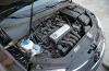
ZAZ-968M engine
Engine the car - carburetor, four-stroke, overhead valve, air-cooled, with a V-shaped arrangement of cylinders. The crankshaft housing is cast from magnesium alloy; the cylinders are removable, cast iron, with a deeply ribbed surface. Pistons - aluminum, tinned. The crankshaft is cast from ductile iron and balanced complete with flywheel, clutch and centrifuge housing. The cylinder head (common for two cylinders) with developed cooling fins is cast from an aluminum alloy.

photo engine ZAZ-968M
Gas distribution mechanism - overhead valve, it consists of gears, a camshaft and a balancing mechanism, as well as pushers, rods, rocker arms and valves. The engine cooling system is air. Air injection is carried out by an axial fan, which consists of a guide vane, cast integrally with blades, in which a groove is provided for installing a generator, fixed with three bolts. At the front end of the generator shaft, a fan drive pulley is fixed, at the rear end - the fan impeller. The generator is driven by a V-belt from a pulley on the engine crankshaft. Air intake for engine cooling is carried out through the grille in the engine compartment hood, additional ventilation of the engine compartment is provided through the slots in the body sidewalls.
The fuel tank is located behind the rear seat backrest. By the way, the spare wheel is also located in the engine compartment of the car. The fuel pump is a diaphragm pump, interchangeable with the VAZ engine pump. Carburetor - type K-133 (for a 40-horsepower engine) or DAAZ-2101-20 (for a 50 hp engine).
The clutch is single-disc, with a damper mounted together with the driven disc in one non-separable unit. The clutch drive is hydraulic. Gearbox ZAZ-968M mechanical, three-way, four-speed - with four forward and one reverse gears. The gearbox is located in the same crankcase with the main gear and differential.

photo of the front suspension ZAZ-968M
Front suspension independent, lever-torsion bar, pivotless, with additional springs mounted on telescopic hydraulic shock absorbers. The suspension is based on an axle, which consists of a pair of steel pipes connected by brackets. Each tube contains one torsion bar consisting of five steel plates; levers are put on the ends of the torsion bars, to which the steering knuckles are connected with the help of ball pins. In the nests of the latter, ball joints are fixed, which ensure the simultaneous rotation of the fist and its movement in the pivot plane. The upper ball pin serves as a support for the shock absorber, in its upper part the shock absorber is attached to the front wheel mudguard. The shock absorber has an additional spring that works in parallel with the torsion bars. 
photo of the rear suspension ZAZ-968M
Rear suspension car independent, spring, double wishbone. Suspension arm steel, stamped, welded in two parts. It is attached to the body floor with a pair of brackets. The elastic suspension element consists of a spring and a telescopic shock absorber. The wheels of the car are steel, stamped - each has a disc and a rim with a 13-inch rim welded to it. The wheels are attached to the front hubs and rear brake drums by four studs using tapered nuts.
Brakes - drum-type with floating shoes and a device for maintaining a constant gap between the drum and the shoes. The drive of the brakes of all wheels is hydraulic, from the foot pedal, separate for the front and rear wheels; the parking brake actuator acting on the rear wheels is mechanical, from the handle.
The steering consists of a steering gear (double roller globoid worm), a pendulum arm and steering rods. The steering shaft is equipped with an energy absorbing element.

Car body bearing, all-metal, two-door. All permanent joints of body parts are formed by resistance welding. In some places, the joints are reinforced with arc and gas welding. In the front part of the body there is a luggage compartment with a lid that can be locked from the inside.
The seats are arranged in two rows. The front seats are separate, movable, with the ability to adjust in accordance with the height of the driver and passenger. The back consists of a pillow and a backrest. The body is equipped with a rear-view mirror, sun visors, independent heating system and rear wheel aprons.
Double-panel doors, stamped. Inside each, a lock and a window regulator are mounted, as well as pivoting and sliding windows. The windshield is made of safety "triplex", back - hardened. The engine compartment hood is suspended on two hinges; in the closed position, the hood is fixed with an internal lock. The luggage compartment hood is hung on two hinged four-link hinges. ZAZ-968M equipped with a heating system that works independently of the car engine, which allows it to be used when the engine is not running.

photo of ZAZ-968M

photo of ZAZ-968M

photo of ZAZ-968M
ZAZ-968MP pickup.

photo of ZAZ-968MP
During 1990-1992, an unusual modification of the base ZAZ 968M was produced - the ZAZ 968PM pickup. It should be noted right away that pickups of a similar design were produced by ZAZ, like any car plant, always for its own internal plant needs (a typical example is ZAZ-965P). However, who got into the series ZAZ-968MP - nothing more than an attempt by the plant to offer the market its own in-plant pickup in the early 90s of the XX century as a delivery vehicle.
In fact, ZAZ 968MP was made according to the slipway-bypass technology - at the rejected or even conditioned (depending on the demand for pickups in a particular period) ZAZ 968M body, the rear part of the cab was cut off and the rear wall with a window was welded behind the front seats. The rear seat was not placed, the resulting niche was the cargo compartment. In order to prevent excessive loss of body rigidity, the top of the cargo compartment was reinforced by welding a U-shaped round pipe, and a corner profile was welded on top of the standard floor around the perimeter of the cargo compartment, which in turn served as the basis for the cargo floor of 10 mm plywood. The body prepared in this way was returned to the conveyor and went in the usual way for painting and subsequent assembly. Of the original parts, perhaps only an awning was used, reinforced along the top of the cargo compartment over its sides. The pickup had a small payload and was inconvenient - there were no drop sides or doors.
It is difficult to say whether the car factory had any particular preferences in terms of the color of these pickups, but most of the cars we met were painted white and only one car was light blue. According to some reports, about 2500 ZAZ 968MP pickups were produced.
In addition, I had to meet mentions of another serial modification of the pickup - ZAZ 968MV. Its differences from the ZAZ 968MP consisted in the factory-installed tubular luggage shelf on the hood cover (the shelf was designed for 50 kg of cargo) and the presence of an awning with a canopy made of rubberized tarpaulin stretched over a collapsible tubular frame.
ZAZ 968M modifications

Few people know that ZAZ also produced a cargo modification of the ZAZ-968M. True, these cars could only be seen on the territory of the car plant or not far from it - in fact, they were in-plant autocars for transporting parts and assemblies between workshops. The autocar had an elongated body with two cargo compartments - in the front, in the standard trunk, and in the middle - between the front seats and the engine compartment. By the way, in the city of Zaporozhye, unlike other cities of the CCCP, ZAZ-968M cars were widely used as police, traveling and service vehicles. 
The first design work to create a new generation car to replace the produced 968 began back in 1970. Dozens of layout options, hundreds of models and layouts, thousands of kilometers traveled by experimental prototypes of prototypes - all this made it possible by 1987 to present to the public as an exhibit of the USSR Exhibition of Economic Achievements a fundamentally new compact front-wheel drive car ZAZ-1102 "Tavria"... Some, however, argued that this original design of ZAZ was also made "based on" an Italian car - this time the Fiat 127 was called the prototype, which had been mass-produced by the concern since 1971. Serial production of "Tavria" was launched in 1988. For some time "Tavria" and "Zaporozhets" were produced simultaneously, but at the end of the 1990s, the production of an obsolete veteran car was discontinued.
You will also be interested in:
With the onset of autumn cold weather, all motorists begin to turn on the interior heater to ...
In a wide list of power units of the German auto giant VAG (Volkswagen AG), FSI engines, ...
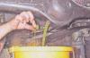
1. Unscrew the filler plug of the rear axle. 2. Substitute under the drain ...

OUR PARTNERS: Website about German cars Lamps used in a car Any ...

The car heater helps to maintain the optimum temperature in the passenger compartment not only ...

