


For normal operation of the clutch mechanism and its drive, it is required to maintain within the required limits the free travel of the outer end of the clutch release fork and the full stroke of the piston rod of the working cylinder when the clutch pedal is pressed to failure.
The free play of the outer end of the clutch release fork is determined by the gap between the thrust bearing and the fifth release levers. This gap should be 2.4 ... 3.4 mm. With insufficient clearance or in its absence, the end of the thrust bearing will contact the heel, which will not make it possible to completely press the pressure plate to the driven one. As a result, slipping of the clutch is inevitable and, as a result, rapid wear of the thrust bearing.
If the specified clearance is too large, then this leads to incomplete disengagement of the clutch (the clutch "leads"), which complicates gear shifting, can cause breakage of the gear teeth and increased wear of the locking rings of the gearbox synchronizer.
As the clutch pads wear out, the thickness of the driven plate decreases. At the same time, the pressure plate approaches the flywheel and the gap between the fifth and the thrust bearing, and, consequently, the free travel of the outer end of the clutch release fork and the clutch pedal decreases. In no case should the free play be adjusted by turning the adjusting nuts 18 (see Fig. 77) of the fingers 19, as this can lead to a skew of the heel / 5 and release levers 16.
The skew of the heel and the levers, in turn, will cause a skew of the pressure plate 5 when the clutch is disengaged, which makes it difficult to disengage the clutch, and the clutch begins to "lead", making it difficult to change gears.
Figure: 80. Clutch release mechanism: 1 - clutch housing; 2, 8 - lower and upper axle bushings; 3 - an axis of a fork with a lever assembly; 4 - spring; 5 - clutch release fork; 6 - an adjusting washer; 7 - spring ring; 9, 10 - lower and upper tides; 11 - thrust bearing holder; 12 - thrust bearing; 13 - connecting link: 14 - nut; 15 - washer; 16 - fork fastening wedge.
CONSTRUCTION FEATURES OF THE CLUTCH
The car is equipped with a dry single-plate clutch with coil springs located along the periphery and a torsional vibration damper (damper) and a driven disc. The outer diameter of the disc friction linings is 190 mm. The clutch is controlled by a hydraulic release from the foot pedal.
The clutch (Fig. 77) consists of two main parts: a pressure plate 5 assembled with a cover and clutch release levers and a driven plate 4. The discs are enclosed in a cast crankcase 10 in the shape of a bell.
To reduce wear, the working surfaces of the support washers and the heel 15 are impregnated with a solid lubricant-molybdenum disulfide during the manufacturing process. The clutch mechanism is housed in a stamped steel casing, connected to the engine flywheel by two locating pins and six bolts with spring washers.

Figure: 77. Clutch: 1 - flywheel; 2 - lock washer; 3 - clutch mounting bolt; 4 - driven disk; 5 - pressure plate; 6 - spring; 7 - flywheel bolt; 8 - clutch release thrust bearing; 9 - cuff; 10 - clutch housing; 11 - transmission drive shaft; 12 - roller bearing; 13 - bearing collar; 14 - plug; 15 - heel; 16 - lever; 17 - persistent rack; 18 - pin adjusting nut; 19 - finger; 20 - spring plate of the driven disk arising from instantaneous dynamic loads with a sharp change in speed.
The pressure plate with the casing assembly is statically balanced, the permissible unbalance is no more than 20 g-cm. The increased imbalance is eliminated by drilling metal in the radial direction along the outer diameter of the pressure plate 10. The metal is removed with a drill 7 mm in diameter (drilling depth up to 6 mm) with a distance from the working end of the disk to the drilling center of 6 mm.
When balancing, the pressure plate (Fig. 78) is installed on the control holes a. After balancing, marks b are applied to the pressure plate and casing to prevent displacements during reassembly and imbalance at the same time. Marks b are applied on one of the protrusions of the pressure plate and on a flat area of \u200b\u200bthe clutch housing surface.
The driven disk (Fig. 79), transmitting rotation from the engine to the transmission drive shaft, has a damper (damper) designed to eliminate the harmful effects of torsional vibrations of the engine crankshaft in the vehicle transmission, as well as to reduce the stresses in the transmission elements,

Figure: 78. Clutch pressure plate with casing, assy:
1 - casing assembly; 2 - pressure disk with three projections; 3 - support washer; 4 - an adjusting nut; 5 - finger of the pressure disk; 6 - persistent lever arm; 7 - pressure plate lever; 8 - heel of levers; 9 - a glass of the clutch pressure spring; 10 - thermal insulation gasket; 11 - pressure spring; 12 - heel spring; a - control holes; b - marks on the casing and disk during static balancing; B - drill a hole with a diameter of 7 mm to a depth of 6 mm with a free distance between the centers; D - when drilling, maintain a size of 6 mm.
After assembly, the driven disc is statically balanced: the permissible balance is no more than 15 g-cm. The increased unbalance is eliminated by installing balancing weights from the light side into the holes in the driven disc, which are located in the intervals between the spring plates. Balance weights must be installed as shown in fig. 79. To secure the weights, their ends are riveted. Depending on the value of the imbalance of the driven discs, weights with different head heights are used to balance them.
For the manufacture of balancing weights can be used bar steel or brass of any grade that lends itself well to riveting. If necessary, the balance weights can be annealed to facilitate riveting. With static balancing, in the case of a large imbalance, it is allowed to remove the material of the friction linings 2 from the end face 12 up to 2 mm deep (see Fig. 79).
The clutch housing is bell-shaped, made of magnesium alloy ML-5. The closed shape of the crankcase significantly increases the rigidity of the structure, and therefore increases the reliability of the clutch and gearbox. Centering of the clutch housing relative to the engine crankcase is carried out by an annular groove with a diameter of 319 + 0.05 mm, a depth of 5.0 ... 5.5 mm. The seats of the clutch housing and the gearbox housing are processed together, therefore the clutch housing is not interchangeable.
The clutch housing is attached to the gearbox housing with eight studs with nuts and is centered on two control pins. The joint cavities between them are lubricated with UN-25 sealing paste during assembly.
To prevent the penetration of grease from the gearbox housing into the clutch housing, collar 9 (see Fig. 77) is pressed into the central hole in the rear wall of the clutch housing with a low-displacement thread on the working edge, which is directed towards the gearbox housing (towards the oil). When replacing the oil seal, lubricate the lip with gear oil.

Figure: 79. Driven clutch disc assembly: 1 - spring plate; 2 - friction lining; 3, 4 - rivets; 5 - damper spring; 6 - hub; 7 - damper ring; 8 - damper plate; 9 - finger; 10 - driven disk; 11 - place of installation of balancing weights; 12 - places for removing the material of the friction linings during static balancing; B - free size; G - the size in the compressed state under the pressure of the pressure springs
On the inner surface of the rear wall of the crankcase (Fig. 80) there are tides 9 and 10. In the holes of the tides polyamide bushings 2 and 8 are installed and the axle 3 of the clutch release mechanism fork is mounted. Axial movement of axis 3 is set 0.1 ... 0.5 mm by selection of shims 6 and is limited by a retaining ring 7.
On the axis 3 there is a fork 5 for disengaging the clutch, which is secured with a spacer wedge 16 with a spring washer 15 and a nut 14, which is tightened with a force of 2.2 ... 3.2 kgf-m.
The return spring 4 returns the fork 5 with the axis 3 of the fork and the lever when the clutch is engaged and provides free travel of the clutch pedal. Spring 4 is loosely put on the fork axle 3, one end abuts against the crankcase wall 1, and with the other, with a special mustache, grabs the fork 5.
In the solution of the fork 5, there is a cast-iron cage 11, into which a sealed ball bearing for disengaging the clutch with a graphite thrust bearing is pressed in. During operation, the thrust bearing does not require additional lubrication. The yoke 11 of the thrust bearing is fixed to the fork 5 by means of two spring connecting links 13.
Before assembly, the inner surface of the bushings 2 and 8, as well as the bearing surfaces of the fork 5, must be lubricated with grease No. 158 or lithol-24.
RUNNING IN THE ENGINE
After repairing the engine, especially in the case of replacing parts of the crank mechanism, it is necessary to run it in before starting operation. The reliability and durability of the engine depends on the thoroughness of the running-in, no less than on the quality of the repair. The engine running-in process consists of two stages.
The first stage is running-in idling for 35 minutes in the following modes:
1000 ... 1200 rpm - 5 min;
2000 ... 2200 rpm - 5 min;
3000 ... 3200 rpm - 10 min;
1000 ... 3600 rpm - 15 min
The engine is run in on M8G1 oil or other oils specified in this book. Keep the carburetor choke fully open. During the first stage of running-in, it is necessary to check the pressure in the lubrication system, there is no leakage, adjust the crankshaft speed at idle, and make sure that it works by ear. The oil pressure at 3000 rpm of the crankshaft and the oil temperature of +80 ° C must be at least 2 kgf / cm2. The malfunctions found during the break-in process should be eliminated and the oil in the oil sump changed.
It is better to carry out the first stage of running-in at the stand, but in the absence of a stand, it is also possible by car.
The second stage is running-in on a car for a run of 3000 km. During this period, it is necessary to follow the rules of running-in a new car, set out in the operating manual.
REPAIR OF THE POWER SYSTEM
Checking the condition of the fuel tank. The fuel tank must be removed and flushed periodically. To remove the tank, release the clamp on the fuel carrier tube and remove the rubber hose from the tube. Disconnect the wire from the fuel level sensor. Then release the clamp // (see Fig. 26) of the seal 12 and remove the fuel tank cap from the neck. Unscrew two bolts / and raise the clamps 2 upwards. Lubricate the upper part of the tank neck with soapy water, after which the tank can be easily removed from the body.
The fuel tank requires repair in case of mechanical damage and contamination. During repairs, the fuel tank is washed in a 5% caustic soda solution, followed by three rinsing with hot water.
Corrosion products are removed by etching in 10% hydrochloric acid solution. After etching, the tank is neutralized with a 20% soda solution and washed with hot water. The tightness of the tank is checked in a bath of water with air at a pressure of 0.2 kgf / cm for 3 minutes. Cracks and other damage to the tank are most easily and safely repaired with epoxy pastes.
Checking the condition of the fuel lines. To prevent fuel leakage in the connecting fittings, tighten them in time. Tighten carefully, as overtightening can damage the threads and tube. If the fuel leak is not eliminated by tightening the nuts, the connection is disassembled and inspected. If necessary, flare the tube cone more or replace the corresponding fixing parts.
Damage to the fuel pipes (crushing, kinks) is eliminated by removing the damaged area with the subsequent connection of the joint using a coupling or an overlap. The joints are soldered with solder to ensure tightness.
Removal, disassembly, inspection and assembly of the fuel pump. When disassembling the fuel pump, the inlet and outlet fuel lines are disconnected from the fuel pump fittings, having previously blocked the access of fuel from the fuel tank. Remove the fuel pump, spacer, rod guide with pump drive rod and fuel pump gaskets. Check the integrity of the spacer and the absence of play of the drive rod in the guide.
Unscrew (see Fig. 27) the screws securing the upper part 5 of the fuel pump body to the lower part 13 and remove the upper part, having previously marked the relative position of the bodies. Unscrew the cover bolt 1, remove the sealing washer, cover and gasket with filter mesh. The lid and mesh are washed. Check if there are no breaks in the mesh, as well as the condition of the inlet 4 and delivery 25 valves in the upper part 5 of the pump housing. If damage is found, replace the upper part of the body together with the valve assembly. Press on the upper cup 6 of the diaphragm 8 of the pump and, turning it 90 °, remove the diaphragm rod from the groove of the balance bar 14, remove the diaphragm 8 assembled with the rod and the central spring of the diaphragm.
The diaphragm is checked to see if there are any tears, cracks or other damage. If necessary, tighten the nut on the diaphragm stem. If damage is found, replace the diaphragm. The diaphragm consists of three layers of rubberized fabric: the top two, working in contact with the fuel. and one in contact with oil.
The central spring of the diaphragm is checked: the free length is 46.5 ... 47.5 mm, under a load of 3.2 ... 3.35 kgf - 24 mm.
Further disassembly of the fuel pump (see Fig. 27) is performed in case of oil leakage through the eccentric 15, axle 16, or in case of malfunctioning of the manual drive. Using the mandrel, the axle 16 of the lever and the balancer is pressed out of the lower housing, the balancer 14, the drive lever 17, the adjusting washers and the lever return spring are removed. The axle should fit snugly in the housing and be free of noticeable wear. Replace parts if necessary. The spring of the drive lever in a free state should have a length of 27.5 ... 28.5 mm.
They clean the eccentric rivets by carefully bending the lever, remove it and the lever spring from the eccentric. Take out the eccentric from the lower body. The parts are inspected and, if damage is found, the unusable ones are replaced. The eccentric O-ring must not be permanently deformed. The ring has an inner diameter of 6.02 ... 6.88 mm, in section it is a circle with a diameter of 1.70 ... 1.86 mm. Before assembling the pump, replace all gaskets and seals with new ones. Before installing new gaskets, they must be lubricated with a thin layer of oil.
The assembly of the fuel pump is performed in the reverse order of disassembly, paying special attention to the cleanliness of the parts and protecting the internal cavities from dust and dirt. When tightening the screws securing the upper and lower bodies of the fuel pump, the diaphragm should be pulled down until it stops to obtain the maximum diaphragm travel. After assembly, check the operation of the balancer drive and the hand drive lever. They should turn without jerking or binding. The hand drive lever should return to its original position by the spring when retracted to its maximum distance.
The tightness of the diaphragm is checked by supplying fuel at a pressure of 0.6 kgf / cm2 to the discharge pipe. Leakage is not allowed. The tightness of the valve is checked at a pressure of 0.3 kgf / cm2. When holding for 10 minutes, fuel leakage is allowed no more than 10 cm3.
Before installing the pump (see Fig. 27) by pressing the lever 17 of the drive, it is moved to the beginning of the effective stroke and the distance between the lever and the mating plane of the pump casing is measured. The size of the sinking B should be 1.0 ... 1.5 mm. Install the rod 21 in the guide 20 of the rod so that the flat end of the rod is directed towards the drive eccentric.

Figure: 71. A device for measuring the protrusion of the end of the fuel pump drive rod: 1-flange; 2-bar; 3-nut; 4-indicator; B-size drowning drive arm
Then set the guide 20 of the rod with the rod 21 spacer 22 and spacers 18 and 19 on the studs of the camshaft gear cover and, fixing them, turn the crankshaft until the maximum protrusion of the rod 21. In this case, the rod should be pressed against the pump drive cam. The rod should protrude above the spacer 22 with the spacer 18 by 1.7 ... 2.8 mm more than the drive lever 17 sinks when choosing a free stroke. The protrusion of the bar is adjusted with a set of shims 19.
It is convenient to adjust and measure the protrusion of the end of the rod using the device (Fig. 71).
Dismantling and checking the condition of the air filter of the K-133 and K-133A carburetors. Release the clamps of the two locks (see Fig. 33, a) and separate the filter pan 13 from the housing 7. Remove the O-ring 3, valve 1 with spring 4, glass 5 and valve seat 2 from the pan. Drain the contaminated oil and rinse the filter pan with kerosene or gasoline until dust deposits are completely removed. Inspect the filter parts.
The operation of the air filter can sometimes be disrupted due to significant deposits on the nylon packing. In this case, the filter housing with the packing is placed in a bath with gasoline for 5 ... 6 hours, after which it is washed and dried.
Assemble the air filter and check its resistance. The resistance of a clean air filter at an air flow rate of 130 m3 / h should be 240 ... 280 mm wg. Art. Pour 0.2 liters of fresh engine oil into the filter pan and finally collect the filter. When assembling, pay attention to the safety of the O-ring and the correct installation of the valve with spring and glass.
Removal, inspection and installation of the air filter of the DAAZ 2101-20 carburetor. Loosen the clamp 17 (see Fig. 33, b), unscrew the nuts of the bracket 29 and remove the filter. The nuts 19 are unscrewed, the cover 20 is removed, the contaminated filter element 21 is taken out and replaced with a new one, before this the housing 23 is cleaned of dust.
The filter element is replaced every 10,000 km. With constant driving on very dusty roads, such a replacement is done every 800 ... 1000 km of run.
It is allowed to reuse the filter element after shaking off the dust and thoroughly blowing it from the inside with dry compressed air (directing the flow perpendicular to the plate on which the filter is installed). It is forbidden to direct the air stream directly onto the filter curtain of the element in order not to damage it. The filter element can be purged without removing it from the housing by directing the air flow through the cover opening perpendicular to the wall.
When assembling the air cleaner, it is necessary to pay attention to the reliability of the seal of the branch pipes in order to avoid the suction of contaminated air.
Disassembly and assembly of a single-chamber carburetor (K-133 and K-133A). It is recommended to disassemble the carburetor in the following sequence:
unscrew the plug 77 of the fuel filter and remove the filter (see Fig. 28);
unscrew the screws securing the cover of the float chamber to the body of the float chamber, lift the cover and, carefully turning it towards the location of the rigid rod, remove the cover with the float from the body of the float chamber; at the same time disconnecting the rod from the choke lever;
remove the gasket, take out the axle 4 (Fig. 72) of the float and remove the float. Remove the valve needle 7 together with the rubber sealing washer 8 and unscrew the valve seat 6. Unscrew the idle air jet 12 (see Fig. 29);
rinse the parts in gasoline. In the presence of abundant resinous deposits, rinse the parts with acetone or nitro paint thinner. To clean the jets, you can use a sharpened wooden stick abundantly moistened with solvent. Blow out the washed parts and channels of the carburetor with compressed air. It is not recommended to flush the fuel valve with acetone or other solvents in order to avoid destruction of the sealing rubber washer. It is completely unacceptable to use wire, even soft wire, to clean the jets;
check the float for leaks. When brazing the float, proper precautions must be taken to avoid explosion of gasoline vapors. After soldering, the mass of the float should be 13.3 ± 0.7 g. Check the fuel valve for leaks. If necessary, replace the sealing rubber washer 8 (see Fig. 72) or the complete fuel valve.

Figure: 72. Float with a fuel valve: 1 - float; 2 - tongue for level setting; 3 - float travel stop; 4 - axis of the float; 5 - float chamber cover: 6 - fuel supply valve seat; 7 - needle of the fuel supply valve; 8 - sealing rubber washer
Assemble the cover of the float chamber in the reverse order of disassembly, while:
the idle air jet must be wrapped up without much effort, checking the safety of the fiber pad;
in case of replacement of parts of the float mechanism or if the carburetor overflows were observed in operation, check the correct position of the float relative to the fuel valve. This position determines the fuel level in the float chamber. Pre-set the size 39 mm by bending the tongue 2 (see Fig. 72). At the same time, it is necessary to set the needle stroke of the fuel supply valve to 1.2 ... 1.5 mm by bending the limiter 3 of the float stroke. In this case, it is not allowed to press the float on the valve needle when adjusting the fuel level in the float chamber in order to avoid damage to the sealing rubber washer;
the circumferential gap between the air damper and the cover body should not exceed 0.25 mm. Followed by:
unscrew screws 40 (see Fig. 29) and remove microswitch 39; disconnect the housing of the mixing chamber and at the same time, pressing on the accelerating pump drive bar, remove the drive rod link connecting the rod with the throttle shaft lever, unscrew the fuel supply screw 4 and remove the accelerator pump sprayer 3;
remove the rod 33 of the accelerating pump drive together with the bar and the piston and remove the rod return spring. Remove the safety ring of the non-return valve from the well of the accelerating pump (using tweezers) and, turning the body of the float chamber, remove the non-return valve 30 (ball d \u003d 4 mm); unscrew plugs 13 (see Fig. 28) of the idle fuel jet and air jet 16 of the main metering system, then unscrew the jets. Turning out the jets, you should use carefully tucked screwdrivers so as not to damage the slots;
unscrew the plug 8 and remove the emulsion tube 9 (see Fig. 29), unscrew the valve 31 of the mechanical economizer and remove the fiber washer;
unscrew the adjusting screw 19 from the mixing chamber housing, unscrew the screws, remove the forced idle economizer 23 (EPCH) and remove the spray gun 25 of the autonomous idle system. Check the tip of the adjusting screw 19 АСХХ and the tapered surface of the hole, the tapered surfaces of the valve 24 of the forced idle economizer (EPCH) system and the spray gun 25 АСХХ, the tightness of the nozzle 25 in the mixing chamber 28, the condition of the valve diaphragm 24 АПХХ. Replace worn-out parts;
check the tightness of the screws securing the throttle valve to the axle. Check the fit of the throttle valve to the mixing chamber housing; the contour gap should not exceed 0.06 mm. Rinse and blow thoroughly all parts. Check if the accelerator pump piston moves easily in the cylinder. It should move in the cylinder without jamming;
check the tightness of the discharge valve of the accelerator pump and the valve of the mechanical economizer (in case of increased gas consumption), inspect the gaskets: replace damaged gaskets with new ones.
Assemble the body of the float chamber with the body of the mixing chamber in the reverse sequence to disassembly, while it is necessary:
wrap the jets without much effort;
ensure the reliability of the seal in all places where the gaskets are installed;
check the gap between the adjusting nuts at full throttle; for the economizer drive rod, it should be 4.5 ... 5.5 mm, and for the piston drive rod of the accelerating pump - 1.5 ... 2.5 mm. Fix the position of the adjusting nuts by squeezing;
install (see Fig. 29) spray nozzle 3 and tighten the fuel supply screw 4,
install the assembled float chamber cover by connecting the rod;

Figure: 73. Device for checking the fuel level in the float chamber of the K-133 and K-133A carburetors: 1 - scale bar; 2 - glass tube; 3 - fitting; 4 - gasket; 5 - carburetor
check the fuel supply by the accelerating pump, which should be at least 6 cm3 in 10 working piston strokes, the relative position of the air and throttle valves;
set the lower stop of the throttle lever so that the throttle valve is fully closed, but does not wedge, and the upper stop so that the plane of the throttle valve is parallel to the axis of the 32 mm hole in the mixing chamber. With the air damper fully closed, the gap between the mixing chamber wall and the throttle valve should be 1.6 ... 1.8 mm (if necessary, set by bending the rod);
install microswitch 39 so that its pusher is recessed by lever 41 when the throttle valve is fully closed
the microswitch drive (microswitch is open), while a characteristic click is heard, when the throttle valve is opened, lever 41 is lowered by 3 ... 4 mm, the microswitch pusher is retracted by a spring, and the microswitch closes;
check the fuel level in the float chamber on the bench. The fuel level in the float chamber at an overpressure of 0.3 kgf / cm2 for gasoline with a density of 0.720 ... 0.750 g / cm3 should be 21 ... 23.5 mm from the upper plane of the float chamber.
In the absence of a stand, this check can be performed with less accuracy on the engine, for which a fitting with a glass tube is made (Fig. 73). It is necessary to unscrew the plug of the main jet and screw the fitting in its place so that the glass tube becomes vertical, then the manual priming lever of the fuel pump. Fill the float chamber with fuel. A metal ruler is used to measure the distance from the upper plane of the float chamber to the fuel level in the float chamber (to the bottom of the meniscus). When installing the carburetor, pay attention to the integrity of the gaskets. After installation, it is required to adjust the carburetor while the engine is idling.
Checking the solenoid valve. The tightness of the solenoid valve should be checked by supplying air at a pressure of 0.9 ... 0.85 kgf / cm2 to the side fitting, with the ventilation fitting closed.
When a vacuum of 0.85 kgf / cm2 is applied to the vertical union, the solenoid valve should open with a 12 V voltage connection and close with voltage removal. If the voltage is connected when the engine is not running, a characteristic click should be heard.
With an engine idling, the valve is checked by disconnecting the wire, while the engine should stop.
Checking the electronic control unit. The electronic control unit has two limit limits. When the engine crankshaft speed increases over 1500 ... 1800 rpm, the positive potential is disconnected at terminal 1 (see Fig. 29), when the frequency decreases below 1500 rpm, a positive potential appears at terminal 1.
Thus, the unit's operability is checked, and before that it is necessary to remove the wires on the microswitch 39. The absence of a positive potential at terminal 1 (if there is a positive potential at terminal 2) signals a unit malfunction and the need to replace it.
In case of failure of the forced idle economizer system, you need to de-energize the system and connect fittings 3 and 6 (see Fig. 28) with a flexible hose, while the carburetor will work according to the generally accepted scheme, without solenoid valve 21 (see Fig. 29) of the electronic control unit 35 and microswitch 39.
Adjusting the carburetor when the engine is idling. Economical engine operation is largely dependent on correct carburetor adjustment when operating at low engine speeds at idle.
This adjustment is carried out with the engine fully warmed up. The oil temperature must be at least 60 ... 70 ° C.
The adjustment of the K-133 and K-133A carburetors must be performed in the following sequence:
with the engine not running, screw in screw 7 (see Fig. 28) of the operating adjustment and screw 2 to failure, but not tightly, so as not to damage their working cones. After that, unscrew the screws 2.5 ... 3 turns;
start the engine and turn the screw 2 to set the crankshaft rotation speed to 950 ... 1050 rpm;
then tighten the screw 7, while the engine crankshaft speed will first increase, and then, with further screwing in the screw, the mixture becomes leaner and the engine will start to work intermittently with a simultaneous decrease in the engine crankshaft speed. At this moment, you need to slightly unscrew the screw 7 and achieve stable engine operation.
The selected adjustment must be checked in variable modes - sharply press the throttle actuator pedal and quickly release it. In this case, the crankshaft rotational speed should increase smoothly without failures and interruptions, and with a sharp release of the pedal, it should decrease to a minimum and stable, while the engine should not stop. If the engine has stopped by unscrewing the screw 7, the speed should be slightly increased.
Checking the emission of harmful substances with exhaust gases into the atmosphere is carried out after adjusting the idle speed on a warm engine (oil temperature 60 ... 70 ° C).
For verification, special equipment is required - a gas analyzer with an error of no more than ± 2.5%. The check is carried out in accordance with GOST 17.2.2.03-87 in two modes: at idle speed and 2550 ... 2650 rpm.
If the emission of harmful substances does not exceed the permissible limits, the toxicity screw 2 (see Fig. 28) of the K-133 and K-133A carburetors must be painted over with red paint. If the emission of harmful substances is above the permissible limits, it is necessary to adjust the engine speed at idle speed and then check the emission of harmful substances.
If the additional adjustment fails to reduce the emission of harmful substances, the carburetor must be replaced and the emission of harmful substances must be checked; upon receipt of unsatisfactory results, diagnose the engine, identify and eliminate the detected faults.
Removal and installation of the DAAZ 2101-20 carburetor. To remove the carburetor, loosen the clamps and remove the crankcase ventilation hose. Unscrew the four nuts securing the outlet pipe, loosen the clamp, remove the pipe with the gasket, and remove the fuel supply hose from the carburetor pipe and close the hose with a stopper to prevent gasoline leakage.
Disconnect the air damper drive cable from the carburetor and the thrust and return spring from the throttle drive lever, unscrew the carburetor mounting nuts, remove it together with the gasket and close the intake manifold inlet with a plug.
Install the carburetor in the reverse order of removal. After installation, it is necessary to adjust the air damper and carburetor throttle drives, as well as the crankshaft speed when the engine is idling.
Dismantling, checking and assembling the DAAZ 2101-20 carburetor. The carburetor is disassembled into the following main units: housing cover assembly with a starting device, a float, a needle valve and a filter; body assembled with diffusers and accelerator pump; throttle body assembly with throttle valves and spool device for crankcase ventilation.

Figure: 74. Details of the cover and the body of the throttle valves of the DAAZ-2101-20 carburetor: 1 - adjusting screw; 2 - cover; 3, 17, 21, 34 - springs; 4 - diaphragm; 5 - diaphragm rod; 6 - the body of the starting device; 7 - telescopic rod; 8 - the axis of the air damper; 9 - air damper; 10 - carburetor cover; 11 - gasket; 12 - carburetor body; 13 - axis of the secondary throttle valve; 14 - axis of the primary throttle valve; 15 - throttle valve; 16 - screw for adjusting the mixture composition; 18 - fitting to the vacuum corrector of the breaker-distributor; 19 - spool; 20 - stop screw; 22 - lever of the primary throttle valve axis; 23 - linkage lever with a starting device; 24 - bushing - 25 - secondary throttle valve drive lever; 26 - dampers drive lever; 27 - lock washer; 28 - return spring of the secondary throttle actuator lever; 29 - starting device thrust; 30 - lever of the secondary throttle valve; 31 - throttle valve body: 32 - gasket; 33 - thrust starting device
Before disassembling, wash the carburetor from the outside and blow it out with compressed air. Disassembly is recommended in the following order:
remove the spring 28 (Fig. 74) of the lever 25 of the throttle valve drive of the secondary chamber, unpin and disconnect from the lever 23 of the throttle valve rod 29 connecting the throttle valve of the primary chamber with the starting device;
pressing the inner cylinder of the telescopic rod 7 into the outer one, disconnect it from the choke control lever;
remove the carburetor cover with the gasket, being careful not to damage the gasket and the float, then unscrew the screws securing the throttle body to the carburetor body and carefully, without skewing, separate them, taking care not to damage the adapter sleeves of the carburetor fuel-air channels and the bushings pressed into the body. Carefully detach the thermal insulation from the housing and remove it;
disassemble the carburetor housing cover in the following order: carefully push the axle 20 (Fig. 75) of the float out of the struts with a mandrel (push towards the struts with a cut) and remove the axle, remove the float 19 and the needle valve 16, the cover gasket. Unscrew the seat 15 of the needle valve, unscrew the plug 18 and remove the fuel filter 17;
disconnect (see Fig. 74) from the lever of the axle 8 of the air damper telescopic rod 7 and rod 33 of the starting device drive;
remove the starting device housing 6, the air damper 9 from the axle, and then remove the axle from the carburetor cover. The ends of the air damper mounting screws are bent. It can take a lot of force to unscrew them and the damper shaft can be deformed. In order to prevent deformation of the axle, it is recommended to put some kind of support under it.
After disassembly, wash the parts in gasoline, blow them with compressed air and check their technical condition, which must meet the following requirements:
the sealing surfaces of the cover must not be damaged, otherwise the cover must be replaced;
the float should not have any damage and any distortion of its shape; the mass of the float should be 11 ... 13 g;
the seat of the needle valve and the valve itself should not have wear on the sealing damage; the needle valve should move freely in its seat; the ball of the needle valve should move freely and not hang.
If damaged parts are found during inspection, they must be replaced.

Figure: 75. Details of the body of the DAAZ-2101-20 carburetor: 1 - screw for fastening the cable sheath; 2 - bracket; 3 - cable fastening screw; 4 - air damper drive lever; 5, 25, 32 - springs; 6 - fuel jet of the secondary chamber transition system; 7 - jet body; 8 - small diffuser; 9 - spray pump accelerator; 10 - valve-screw of the pump-accelerator; 11 - valve; 12 - main air jet of the secondary chamber; 13, 22 - emulsion tubes of the secondary and primary chambers; 14 - main air jet of the primary chamber; 15 - needle valve saddle; 16 - needle valve; 17 - filter; 18 - cork; 19 - float; 20 - axis; 21 - adjusting screw of the accelerator pump; 23 - main fuel jet of the primary chamber; 24 - main fuel jet of the secondary chamber; 26 - diaphragm of the pump-accelerator; 27 - pump accelerator cover; 28 - jet body; 29 - idle fuel jet: 30 - carburetor body; 31 - throttle valve opening adjustment screw; 33 - locking spring; 34 - toxicity screw; 35 - plug.
Next, disassemble the starting device, while unscrewing (see Fig. 74) three screws securing the cover 2 of the device, remove the cover with the adjusting screw 1, spring 3 and diaphragm 4. After disassembly, all parts of the starting device are cleaned, washed with gasoline, blown with compressed air and inspect - replace damaged ones with new ones. When disassembling the throttle body, it is necessary to unscrew the screw 16 for adjusting the idle air mixture, unscrew the screws holding the throttle bodies 15 to the axles, and remove the throttle valves from the axles. The ends of the throttle valve mounting screws are bored, therefore, when unscrewing the screws, as well as when removing the air damper, it is recommended to install a support under the throttle axles.
Next, the nut securing the levers on the throttle valve axis of the primary chamber is unscrewed, the lock washer, levers 26, 25, 23 with washers and bushing 24 are removed from the throttle valve axis of the primary chamber, and then the spool spring 21 and spool 19.
The axle 14 of the throttle valve of the primary chamber is removed from the housing 31, the nut securing the lever 30 on the axis of the throttle valve of the secondary chamber is unscrewed, the lever with the washer is removed and the axle 13 of the throttle valve of the secondary chamber is removed.
Clean the parts and rinse them with gasoline or acetone. It is recommended to wash the channels and parts of the spool valve crankcase ventilation with a mixture of 30% ethylene ether glycol monobutyl and 70% gasoline. Inspect parts, replace damaged ones.
The choke axle holes are cleaned with a reamer having a diameter equal to the nominal hole diameter (8.020 ... 8.042 mm).
If the holes are badly worn, then it is necessary to expand them to a diameter of 8.520 ... 8.542 mm (0.5 mm more than the nominal) and during assembly install the axes of the repair size, increased in diameter by 0.5 mm.
unscrew the screw securing the lever 4 of the air damper drive, remove the lever, spring 5, remove the cover 27 of the accelerator pump with a return spring 25;
unscrew the main air jets 12 and 14, turn the body over and, gently tapping on it, shake out the emulsion tubes 13 and 22 from the wells, then unscrew the nozzle bodies 7 and 28 and remove them together with the nozzles 6 and 29, unscrew the valve screw 10 and remove the nozzle 9 the accelerator pump with gaskets, then unscrew the adjusting screw 21 of the accelerator pump and the screw 31 for adjusting the opening of the throttle valves and remove the small diffusers 8, unscrew the main fuel jets 23 and 24 and remove the bracket 2, on which the sheath of the air damper control cable is attached ; remove cap 35 and unscrew screw 34 with spring 33.
The carburetor body is cleaned of dirt and oil. The body and its channels are washed with gasoline or acetone and blown with compressed air. If necessary, clean channels and emulsion wells with special sweeps. Inspect the sealing surfaces of the housing; if damaged, the housing should be replaced.
Parts of the accelerator pump are cleaned, washed and blown out with compressed air. Check the ease of movement of the ball in the valve screw 10 (see Fig. 75) and the condition of the sealing surfaces and gaskets. Check the ease of movement of the moving elements of the pump (lever, roller, diaphragm parts). Jamming is not allowed. The diaphragm must be intact and free from deformation. Even a slight deformation of the diaphragm affects the operation of the pump. Replace damaged parts with new ones.
The jets and emulsion tubes are cleaned of dirt and resinous deposits, washed with acetone or gasoline and blown with dry compressed air. Comparison of the jets for throughput with the reference.
It is not recommended to clean the jets with a metal tool or wire, as well as wipe the jets and other carburetor parts with cotton wool, cloth or rags. In case of severe clogging, the jets should be cleaned with a soft wood needle, abundantly moistened with acetone.
The carburetor is assembled in the reverse order of the design. In this case, the float should rotate freely on its axis, without touching the walls of the chamber, the needle valve should slide freely in its seat, without distortions, the valve leash should not interfere with the movement of the float tongue.
When installing the air damper and throttle dampers, the ends of the fastening screws must be bent out using a stand similar to that used during disassembly. After assembly, the carburetor assemblies must be adjusted.
Adjustment of the DAAZ 2101-20 carburetor. The position of the throttle valve of the secondary chamber is adjusted (see Fig. 31, b) with the screw 27. In the position of the lever 28 corresponding to the full closure of the throttle valves, the throttle valve of the secondary chamber should be slightly open. The gap between the throttle valve and the chamber wall at the exit of the transition system channels should be no more than 0.02 ... 0.03 mm.
In the position of the lever 28, in which the protrusion of the sector 29 is in contact with the lever 31, the throttle valve of the primary chamber should be slightly open by (7 ± 0.25) mm. This gap can be obtained by bending the protrusion of the sector 29. Both throttle valves should be fully open when the lever 28 is turned to the extreme position until the stop of the sector 29 in a special lug on the throttle body. This position of the throttle valves is adjusted by folding the lower protrusion of the sector 29.
The starting device is adjusted as follows (see Fig. 31, b). When the lever 20 is turned counterclockwise until it stops, the air damper should be completely closed, and in this position of the lever, the end of the rod 22 should be at the end of the groove in the diaphragm 23 of the starting device, but it is not allowed to move the rod. This requirement is met by 1 liter by bending the rod 22. When the air damper is fully closed, the throttle valve of the primary chamber should be covered by 1.2 ... 1.3 mm (the distance between the throttle valve and the chamber wall at the idle speed transition holes). This gap is adjusted by bending the rod 35. A fully closed air damper should open by (7 ± 0.25) mm by the diaphragm rod 23 of the starting device when it is manually moved to the right until it stops. This gap is adjusted with screw 24.
The performance of the accelerator pump is checked for 10 full turns (strokes) of the throttle valve control lever 28, the fluid released from the sprayer 45 (see Fig. 31, d), during these 10 strokes is collected in a beaker. Its volume should be 5.25 ... 8.75 cm3.

Figure: 76. Setting the fuel level in the melting chamber of the DAAZ 2101-20 carburetor: 1-carburetor cover: 2-needle valve seat; 3-needle valve; 4-stop; 5- needle valve ball; 6-pin valve needle plug; 7-float bracket; 8-tongue; 9-float; 10-gasket.
Before starting the check, it is necessary to make 10 test strokes with lever 28 (see Fig. 31, b) to fill the channels of the accelerator pump.
The tightness of the needle valve is checked on a bench that supplies fuel to the carburetor under a pressure of 3 m of water. Art. After setting the level in the test tube of the stand, its fall is not allowed for 10 ... 15 s. If the fuel level in the test tube drops, this indicates a fuel leak through the needle valve.
Setting the fuel level in the float chamber. For DAAZ 2101-20 carburetors, checking the fuel level in the float chamber is not provided.
The level necessary for the normal operation of the carburetor is ensured by the correct installation of serviceable elements of the locking device (Fig. 76): the float assembly should not have any visible damage, the mass of the float should be 11 ... 13 g; the distance between the float and the gasket 10 adjacent to the carburetor cover should be (6.5 ± 0.25) mm.
The control is carried out with a gauge, the body cover is held vertically so that the tongue 8 of the float lightly touches the ball 5 of the needle valve 3, without sinking it: the size (6.5 ± 0.25) mm is adjusted by bending the tongue 8, while it is necessary that the support platform the uvula was perpendicular to the axis of the needle valve and had no nicks or dents; the gap corresponding to the maximum float stroke should be (8 ± 0.25) mm. It is adjusted by bending the stop 4, the fork 6 should not interfere with the free movement of the float. After installing the carburetor, make sure that the float does not touch the walls of the float chamber.
The correct fit of the float should be checked each time the float or fuel needle valve is replaced; when replacing the needle valve, the valve gasket must be replaced.
Adjusting the speed of the crankshaft at idle. The elements that regulate the speed of the crankshaft when the engine is idling include (see Fig. 30) screw 11 of the mixture composition and screw 2, which limits the opening of the throttle valve. When screwing in screw 11, the mixture becomes leaner, when screwing in screw 2, the throttle valve opens slightly. A limiting plastic sleeve is pressed onto screw 11, which allows the screw to be turned only one turn. Therefore, before adjusting at a service station, it is necessary, by unscrewing the screw 11, to break the protrusion of the bushing, unscrew the screw, remove the bushing from it and screw the screw back into the carburetor. After completing the adjustment, press a new restrictive plastic sleeve onto screw II in such a position that the protrusion of the sleeve, touching the stop in the hole, does not allow the screw to be removed.
Idling is adjusted on a warm engine (oil temperature 60 ... 70 ° C) with adjusted gaps in the gas distribution mechanism and with a correctly set ignition timing.
The adjustment is carried out in the following sequence (see fig. 30):
with screw 11, set the maximum crankshaft rotation speed at this position of the throttle valve, and then with screw 2 set the minimum stable crankshaft rotation speed;
with screw 11, achieve a CO concentration in the exhaust gases of no more than 1.5% at a given position of the throttle valve and with screw 2 restore the crankshaft speed to 950 ... 1050 rpm;
set the crankshaft speed at idle speed equal to 0.6 rated revolutions (2700 ... 2800 rpm), and check the CO concentration in the exhaust gases, which should be no more than 1%, if necessary, achieve the CO concentration with screw 7. After that, once again check the concentration of CO in the exhaust gases when idling with a crankshaft speed of 950 ... 1050 rpm and achieve a concentration of no more than 1.5%;
put plug 35 (see Fig. 75) into the screw hole. In the absence of a gas analyzer, the adjustment can be carried out in the following order:
set the minimum stable crankshaft rotation speed with screw 2 (see Fig. 30), and then use screw 11 to achieve the engine operation at the maximum crankshaft speed at a given throttle position;
with screw 2, reduce the opening of the throttle valve until the minimum stable speed is obtained and, tightening screw 11, set the crankshaft speed at which the engine runs with noticeable interruptions, and then unscrew the screw by 30 ... 60 ° (no more) until a stable engine operation;
check the adjustment by quickly depressing and releasing the throttle pedal. The engine must not stop at the same time.
Removal and installation of carburetor drives. To remove the throttle actuator rod assembly with a cable and sheath, you must:
unscrew the screw 14 (see Fig. 32) securing the cable to the carburetor rod and release the cable;
unpin the pin, disconnect the cable from the pedal 3 and remove it completely from the tube laid in the floor tunnel; bend the bracket 18 for attaching the shell to the engine bracket;
unscrew the two bolts securing the fuel tank clamps to the body floor (after removing the rear seat) and slightly lift the tank up to release the carburetor linkage shells;
remove the shell from the rubber seals (on the body walls).
Install the throttle cable in the reverse order.
To remove the choke rod from the car, you must release the fuel tank fastener (as described above), and then (see Fig. 32):
disconnect the rod 12 and the shell 9 from the carburetor 13, for which loosen the screws 10 and bolt II;
pull the button 4 of the air damper drive rod and completely remove it from the shell;
disconnect and remove the gearbox control mechanism from the tunnel (see subsection "Gearbox control mechanism") and bend the shell fastening bracket located in the tunnel;
unscrew the two screws 6 securing the bracket 5 to the tunnel and remove the bracket with the shell from the tunnel, then use a screwdriver to separate the shell retainer 7 from the bracket 6.
The air damper control actuator assembly and installation is performed in reverse order.
Adjusting the carburetor drive. After dismantling and installing the drives to the carburetor flaps or installing new ones, appropriate adjustments should be made.
It is recommended to adjust the carburetor throttle control drive as follows (see Fig. 32): loosen the screw (bolt) 14 fastening the rod 17 and tighten the end of the rod with pliers until the pedal 3 is in the uppermost position; fix the rod in this position with a screw. With correct adjustment of the drive, the carburetor throttle valve should be fully closed when the pedal is released and fully open when the pedal is fully depressed.
The air damper actuator should be adjusted in the following order: loosen the bolt (screw) 11 fastening the rod to the carburetor air damper articulated clutch and lower the air damper actuator button 4 to the lowest position; without moving the rods in the shell, open the air damper completely and in this position fix the rod with the bolt (screw) 11. The shell 9 of the rod must be tightly tightened with the screw 10, the shell is not allowed to protrude beyond the bracket.
I continue to walk my yellow zazik, adding variety to the city's traffic flow. As a rule, the operation of a 40-year-old car makes its own adjustments. It happened this time too. Returning on Sunday evening from friends, our path lay through Leningradka with all the attributes of an evening arrival in the city. After 10 km of pushing through traffic jams, closer to the Moscow Ring Road, the clutch pedal began to fail. According to the level of the liquid, a disappointing conclusion was made, the leakage of the liquid and judging by its smell, it is something BSK. On the last remnants of the BSC, the first gear was engaged and continued to move with a huge distance. For some reason, the rest of the traffic participants did not like this style of movement :) And what to do? emergency gang zazik is not equipped.
Having reached the garage when trying to switch the reverse gear, we got a small puddle under the car. We arrived ...
A cursory examination confirmed the primary diagnosis. Lost the clutch slave cylinder. 
I began to slowly disassemble the system. Probably the first time in 40 years :) 
The desire was to switch to a bunker, so I decided to sort out the clutch master cylinder. 
The slave cylinder boot is torn, but this is not a cause, but rather a consequence. As the autopsy showed, it was definitely not the reason. 
Disassembling the master cylinder, shook something out of it. Reminds of plastic shavings, but where are they from? Well, the color of the liquid. 
And here is the cause of the breakdown. The insides of the working cylinder. The upper left rubber band is the cylinder cuff, which holds the pressure in the system and transfers it further to the iron piston. The one that was inside resembled plasticine in properties, but not rubber. This can be achieved by mixing DOT with BSK from this we draw a conclusion. When the fluid level in the clutch expansion tank dropped, without knowing what was in it, a certain amount of pillboxes was added, which killed half of the rubber bands in the system. 
The rubber bands of the master cylinder are more or less in order. By the way, the clutch repair kit that I accidentally found did not have one cuff, and I decided to leave it with the old one, after washing it. Which let me down later. The master cylinder simply leaked through the stem. Elastic band on the piston in the upper left corner. I decided not to fence in the garden and replaced the master cylinder entirely, I also found it by chance :) 
Infernal mixture of pillbox + BSK + xs what. A liter baklahi DOT-4 was enough for everything. 
The clutch (Fig. 77) consists of two main parts: a pressure plate 5 assembled with a casing and clutch release levers and a driven plate 4. The discs are enclosed in a cast crankcase 10 in the shape of a bell.
To reduce wear, the working surfaces of the support washers and the heel 15 are impregnated with a solid lubricant-molybdenum disulfide during the manufacturing process. The clutch mechanism is housed in a stamped steel casing, connected to the engine flywheel by two locating pins and six bolts with spring washers.


Figure: 77. Clutch: 1 - flywheel; 2 - lock washer; 3 - clutch mounting bolt; 4 - driven disk; 5 - pressure plate; 6 - spring; 7 - flywheel bolt; 8 - clutch release thrust bearing; 9 - cuff; 10 - clutch housing; 11 - transmission drive shaft; 12 - roller bearing; 13 - bearing collar; 14 - plug; 15 - heel; 16 - lever; 17 - persistent rack; 18 - pin adjusting nut; 19 - finger; 20 - spring plate of the driven disk arising from instantaneous dynamic loads with a sharp change in speed.
Pressure disc with the casing assembly are statically balanced, the permissible unbalance is not more than 20 g-cm. The increased imbalance is eliminated by drilling metal in the radial direction along the outer diameter of the pressure plate 10. The metal is removed with a drill 7 mm in diameter (drilling depth up to 6 mm) with a distance from the working end of the disk to the drilling center of 6 mm.
When balancing, the pressure plate (Fig. 78) is installed on the control holes a. After balancing, marks b are applied to the pressure plate and casing to prevent displacements during reassembly and imbalance at the same time. Marks b are applied on one of the protrusions of the pressure plate and on a flat area of \u200b\u200bthe clutch housing surface.
Driven disc (Fig. 79), which transfers rotation from the engine to the transmission drive shaft, has a damper (damper) designed to eliminate the harmful effects of torsional vibrations of the engine crankshaft in the vehicle transmission, as well as to reduce the stresses in the transmission elements,
https://pandia.ru/text/78/063/images/image092_0.gif "width \u003d" 586 "height \u003d" 539 src \u003d "\u003e
Figure: 79. Driven clutch disc assembly: 1 - spring plate; 2 - friction lining; 3, 4 - rivets; 5 - damper spring; 6 - hub; 7 - damper ring; 8 - damper plate; 9 - finger; 10 - driven disk; 11 - place of installation of balancing weights; 12 - places for removing the material of the friction linings during static balancing;
B - free size; G - the size in the compressed state under the pressure of the pressure springs
On the inner surface of the rear wall of the crankcase (Fig. 80) there are tides 9 and 10. In the holes of the tides, polyamide bushings 2 and 8 are installed and the axle 3 of the clutch release mechanism fork is mounted. Axial movement of axis 3 is set 0.1 ... 0.5 mm by selection of shims 6 and is limited by retaining ring 7.
On the axis 3 there is a fork 5 for disengaging the clutch, which is secured with a spacer wedge 16 with a spring washer 15 and a nut 14, which is tightened with a force of 2.2 ... 3.2 kgf-m.
The return spring 4 returns the fork 5 with the axis 3 of the fork and the lever when the clutch is engaged and provides free travel of the clutch pedal. Spring 4 is loosely put on the axle 3 of the fork, with one end abuts against the wall of the crankcase 1, and with the other, with a special mustache, grabs the fork 5.
In the solution of the fork 5, there is a cast-iron cage 11, into which a closed ball bearing for disengaging the clutch with a graphite thrust bearing is pressed in. During operation, the thrust bearing does not require additional lubrication. The yoke 11 of the thrust bearing is fixed to the fork 5 by means of two spring connecting links 13.
Before assembly, the inner surface of the bushings 2 and 8, as well as the bearing surfaces of the fork 5, must be lubricated with grease No. 000 or lithol-24.
CLUTCH OPERATION
For normal operation of the clutch mechanism and its drive, it is required to maintain within the required limits the free travel of the outer end of the clutch release fork and the full stroke of the piston rod of the slave cylinder when the clutch pedal is pressed to failure.
The free play of the outer end of the clutch release fork is determined by the gap between the thrust bearing and the fifth release levers. This gap should be 2.4 ... 3.4 mm. If there is insufficient clearance or in its absence, the end of the thrust bearing will contact the heel, which will not make it possible to completely press the pressure plate to the driven one. As a result, slipping of the clutch is inevitable and, as a result, rapid wear of the thrust bearing.
If the specified clearance is too large, this leads to incomplete disengagement of the clutch (the clutch "leads"), which complicates gear shifting, can cause breakage of the gear teeth and increased wear of the locking rings of the gearbox synchronizer.
As the clutch pads wear out, the thickness of the driven plate decreases. At the same time, the pressure plate approaches the flywheel and the gap between the fifth and the thrust bearing, and, consequently, the free travel of the outer end of the clutch release fork and the clutch pedal decreases. In no case should the free play be adjusted by rotating the adjusting nuts 18 (see Fig. 77) of the fingers 19, as this can lead to a skew of the heel / 5 and release levers 16.
The skew of the heel and the levers, in turn, will cause a skew of the pressure plate 5 when the clutch is disengaged, which makes it difficult to disengage the clutch, and the clutch begins to "lead", making it difficult to change gears.
https://pandia.ru/text/78/063/images/image094_0.gif "width \u003d" 523 "height \u003d" 715 src \u003d "\u003e
Figure: 81. Device for disassembling and assembling the clutch: 1 - plate; 2 - support; 3, 6 - screws; 4 - clamping bracket; 5 - clamp handle; 7 - emphasis; 8 - clamp screw
Before disassembly, the clutch is cleaned of dirt and wiped dry.
Install the clutch cover assembly with a pressure plate (see Fig. 78) into the device for disassembling and assembling the clutch and sawing the collars of the adjusting nuts 4 pressed into the grooves of the fingers 5. Unscrew and remove the adjusting nuts 4, support washers 3, heel 8, levers 7 and springs 12.
Unscrew the handle 5 (see Fig. 81) of the device and remove the bracket of the device and the casing 1 (see Fig. 78), cups 9 of pressure springs, pressure springs 11 and thermal insulating gaskets 10. Remove the retaining ring 7 (see Fig. 80) and adjusting washers 6 from the fork axis 3.
The nut 14 is unscrewed, the washer 15 is removed, the wedge 16 is carefully knocked out, the hub axle is removed from the sockets of the clutch housing and the opening of the fork 5 for disengaging the clutch. Remove the return spring 4, two connecting links 13, clip 11 of the clutch release center and bushings 2 and 8. Insert two screwdrivers between the collar of the oil seal and the clutch housing, press out the oil seal of the clutch housing (only if replacement is necessary).
Checking the condition of parts. The need to check the parts of the clutch mechanism usually arises when the friction linings or graphite bearing are worn. The rest of the parts wear out slightly, and their wear does not lead to the loss of the mechanism's performance. When inspecting a disassembled clutch, you must carefully check its parts.
TOclutch artery... The crankcase sealing surfaces must be free from scratches, nicks and cracks. Risks and nicks should be cleaned, if cracks are found, weld or replace the crankcase. Check the dimensions of the bushings and the fork axle (see Appendix 2), the gap between the bushings and the axle should not exceed 0.6 mm. When the gap increases, the bushings are replaced.
Driven disc... It is necessary to make sure that the disc hub can be easily moved along the splines of the transmission drive shaft. If the splines of the hub or shaft are heavily worn (misalignment of the hub in bulk), the worn parts are replaced. The friction linings must not be oily, broken, burnt or worn down to the rivet heads. Otherwise, the pads are replaced, since in the presence of the indicated deviations, the coefficient of friction between the driving and driven elements decreases, which leads to slipping of the clutch when accelerating the car or when the resistance to its movement increases.
Check the condition of the ends on the outer diameter and the elasticity of the springs 5 \u200b\u200b(see Fig. 79) of the damper. At the ends and outer diameter, the springs of the torsional vibration damper should not have any traces of chafing and wear with a depth of more than 0.2 mm. The length of the spring in a free state should be 24.25 ... 24.75 mm, and when compressed with a load of 42 ... 50 kgf - 21.5 mm. The frictional moment in the torsional vibration damper of the clutch driven disc is within 0.375 ... 09 kgf m, while the friction surfaces of the driven disc 10, damper plate 8, hub 6, damper rings 7 must be clean and dry.
When riveting new friction linings, make sure that every second hole in the lining is drilled through, and riveting is carried out in such a way that both linings are individually riveted through one hole in the plate. After riveting the friction linings, the driven disc assembly is checked for beating of the working surfaces of the linings relative to the hub axis (on the mandrel or on the gearbox drive shaft), which should be no more than 0.75 mm, and static balancing is performed. The permissible imbalance is 15 g-cm, which is achieved by installing balancing weights (see item 11 in Fig. 79) or by removing the material of the friction linings.
Check the thickness of the disc assembly in a free state, which should be 8.1 ... 8.7 mm.
Clutch pressure plate... Check the flatness of the working surface of the pressure plate 2 (see Fig. 78). Flatness is allowed no more than 0.05 mm. If there are ring marks on the working surface, the disc must be sanded. Grinding the pressure plate and the associated decrease in its thickness reduces the total working force of the pressure springs 11. To maintain this force, when assembling the clutch, it is necessary to install washers under the thermal insulating gaskets 10. The thickness of the washer should be equal to the thickness of the metal layer removed during grinding. The side surfaces of the three protrusions shall not have more than 0.2 mm wear.
The pressure levers 7 and the working surfaces for the support and the pressure plate heel should not have more than 0.2 mm wear.
Pressure springs. Check the elasticity of the springs. According to the value of the working force required to compress the springs to size
31 mm, they are sorted into two groups: with a working force of 50.5 ... 53.5 kgf, which are marked in brown, and with a working force of 53.5 ... 56.5 kgf, which are marked in green. Pressure springs of the same color are placed on one clutch.
Clutch release bearing... Increased wear of the thrust bearing occurs if the free travel of the clutch pedal is not adjusted during the operation of the car, as well as when the car is not driven correctly, that is, when you unnecessarily keep your foot on the clutch pedal. The surfaces of the cage pivots must not have more than 0.3 mm of wear, otherwise the thrust bearing assembly must be replaced. Inspect the combined ball bearing. If the axial run of the bearing is more than 0.35 mm, the bearing must be replaced.
The presence of grease in the bearing is checked; in the absence of grease (dry rolling of the balls), the bearing is replaced or filled with grease. To do this, without disassembling it, wash it in gasoline and dry it. In the bath, the LZ-31 grease is heated to a temperature of 150 ... 170 ° C and the bearing assembly is placed in it for 15 ... 20 minutes, after that the bath is cooled to a temperature not higher than 50 ° C, the bearing is taken out and wiped outside.
Gearbox drive shaft needle bearing (front). Check the freedom of rotation of the bearing assembly with the bolt. The rotation should be free, without jamming. The bearing is washed and filled with refractory grease No. 000 in the amount of 2 ... 3 g. The grease is introduced from the side of the threaded part of the bolt.
Clutch assembly. The assembly is performed in reverse order, taking into account the following:
installing (see Fig. 77) the collar 9 in the clutch housing 10, it is necessary to lubricate the outer diameter and the working edge of the collar with gearbox oil and check the correct installation of the cuff spring. Then install (see Fig. 80) bushings 2 and 8, lubricating working journals of axle 3 with grease No. 000, collecting it with spring 4 and release fork 5. Tighten nut 14 of wedge 16 (tightening torque 2.2 ... 3.2 kgf-m).
Check and, if necessary, set the axial movement of axis 3 within 0.1 ... 0.5 mm, which is ensured by the selection of washers 6;
install the yoke 11 with the thrust bearing 12 on the fork 5, lubricating the pins of the yoke with grease No. 000, and fix it with brackets;
assemble the clutch pressure plate with the cover. Before assembly (see Fig. 78), lightly grease the bearing surfaces of washer 3, thrust struts 6, levers 7 and heel 8 with grease No. 000;
pre-adjust the position of the heel to a size of 52 mm ± 0.37 mm, do not lock the adjusting nuts 4 (see Fig. 78);
remove the clutch assembly from the device and bleed it by pressing the heel of the levers using a lever or screw press. In this case, the stroke of the heel should be II mm, the number of rolls
Installation and final clutch adjustment. Install a mandrel (you can use the gearbox drive shaft as a mandrel) into bearing 12 (see Fig. 77) of the gearbox drive shaft, wipe the flywheel support surface and install the driven clutch disc along the mandrel splines. Install the disc and casing assembly on the flywheel, aligning the numbers printed on the clutch casing and on the flywheel (see view A in Fig. 77). This preserves the relative position of the parts, which was during the dynamic balancing of the crankshaft assembly with a flywheel and clutch. Attach the clutch with bolts 3 to the flywheel with a tightening torque of 1.6 ... 2 kgf-m.
Prepare a device (see Fig. 42) for the final budding of the clutch heel on the engine. A jumper 2 with an indicator is installed on the mounting plate 5 on the t-rack / foot, setting an interference fit of 0.5 ... 1 mm and aligning the indicator boom with zero. The control post ^ is set to the nominal installation size of the heel equal to 52 mm ± 0.37 mm. A device for checking the runout of the heel is installed on the crankcase studs and secured.
Adjust the position of the heel by size (52 ± 0.37) mm and mutual beating of the plane (see Fig. 77) of the clutch heel relative to the flywheel by unscrewing or tightening the adjusting nuts 18, When adjusting the levers 16 should be moved to the extreme position from the center to the stop in the stop rack 17, that is, there should be no gap in the connection. The runout of the plane b of the heel 15 should be no more than 0.1 mm.
After adjusting the runout of the heel, it is necessary to lock the adjusting nuts 18 by pressing the collar on the nuts into the longitudinal slot on the ends of the fingers 19. After locking the nuts, the runout of the heel should not exceed 0.8 mm.
CONSTRUCTION FEATURES OF THE CLUTCH RELEASE ACTUATOR
The car uses a hydraulic drive for disengaging the Coupling (Fig. 82). The clutch pedal is suspended on an axle with a plastic bushing and is attached to a bracket installed in the trunk of the body. To prevent dust and cold air from entering the body, the pedal is sealed with a rubber slotted seal. In the extreme upper position. the pedal is held by a retractor spring.
The pedal is pivotally connected to the clutch master cylinder by means of a finger, shims are installed between the pedal and the walls of the pusher eyelet, and shims are installed between the master cylinder flange and the bracket. The feed tank is attached to the shelf of the inner panel above the master cylinder.
The main and working cylinders are interconnected by two steel pipelines. The first pipeline runs along the floor tunnel. The transition of the pipeline from the body is carried out through a coupling. The pipeline running from the coupling to the clutch housing has a spiral in the middle part that compensates for the change in the length of the pipeline when the power unit is swinging, suspended on rubber cushions. The slave cylinder is attached to the clutch housing. The lever of the clutch release fork with the help of a retraction spring constantly presses the rod of the working cylinder against the piston and moves the latter to the extreme forward position.
The master cylinder of the clutch release drive (Fig. 83) consists of a cast iron body, a piston made of zinc alloy, with a rubber sealing collar that keeps fluid from flowing out of the cylinder. There are six through holes in the piston head, covered with a thin steel ring - a valve and an internal rubber cuff. The spring presses the collar against the piston, and the piston against the thrust washer held in the cylinder by a retaining ring. The rear end of the master cylinder is closed by a threaded nipple with a gasket. A pusher enters the inner cavity of the piston, which has a fork at the end connected to the pedal. To protect the cylinder from dust and dirt, a rubber boot is used, the rear part of which enters the groove on the cylinder, and the front part wraps around the stem. The clutch master cylinder has an inner diameter of 19 mm.
The clutch slave cylinder (see Fig. 83) has an inner diameter of 22 mm.
https://pandia.ru/text/78/063/images/image096_0.gif "width \u003d" 614 "height \u003d" 474 src \u003d "\u003e
Figure: 83. Main and working cylinders of the clutch release drive: 1 - cap; 2 - valve; 3 - the body of the working cylinder; 4 - spring; 5 - fitting; 6 - washer; 7 - main cylinder body; 8 - plug; 9 - washer; 10 - pusher; 11, 18 - protective caps; 12 - piston; 13 - outer cuff; 14 - thrust washer; 15, 19 - retaining rings; 16 - valve; 17 - inner cuff; 20 - piston; 21 - sealing collar; 22 - adjusting nut; 23 - lock nut; 24 - spacer fungus; pusher; 26 - spring.
unscrew the union 5 of the cylinder and, using a wooden drift, remove the piston with the outer cuff, the piston valve, the inner cuff and the piston return spring from the cylinder.
The disassembled parts of the clutch release drive are thoroughly washed, inspected and determined suitability for further work. Parts of the clutch slave and master cylinders are washed in denatured alcohol, alcohol or fresh brake fluid.
Assembling the clutch release drive is carried out in the reverse order, taking into account the following instructions.
All parts of the working and master cylinders, as well as the inner cavity of the cylinders, must be lubricated with castor oil or fresh brake fluid before assembly. When connecting the pedal 14 (see Fig. 82) with the fork, push the adjusting washers 21 between the fork and the pedal set so that the push rod is aligned with the main cylinder.
The pedal connected to the pusher of the clutch master cylinder must have a full travel of at least 150 mm (travel from the upper limit position to the stop on the floor of the body). If the pedal travel is less than 150 mm, it is necessary to install an additional gasket 27 between the bracket 24 and the support flange of the master cylinder 26. If the pedal travel significantly exceeds 150 mm, remove the gasket.
Clutch pedal free play. The free play of the pedal in the center of its platform is measured with a measuring ruler, while pressing the pedal with a finger until there is a tangible resistance to the movement of the pedal. It should be within 26 ... 38 mm.
To adjust the free travel of the pedal, remove (see Fig. 82) the release spring 5 and turn the lever 4 until the thrust bearing 2 rests against the heel 3 of the release levers, while the stroke of the lever 4 is at the end "(near the working cylinder rod) should be 4 ... 5 mm, which corresponds to the gap between the heel and the bearing 2.4 ... 3.4 mm.If the indicated size is smaller, hold the pusher 8 with a key, release the lock nut 7 and screw the adjusting nut 6 onto the pusher 8 and checking the lever travel, set its free travel within 4 ... 5 mm, then lock the adjusting nut 6 and put on the pull-back spring 5.
Filling the system with liquid and removing air from it. To refuel the hydraulic drive for disengaging the clutch, use the same fluid as for the hydraulic drive of the car brakes.
It is recommended to carry out the work in the following order: fill a clean glass transparent vessel with a capacity of about 0.5 liters from 1/3 to 1/2 height with brake fluid, remove the cap from the filler tank neck and fill it with fluid to the nominal level (see subsection "Brakes ");
clean the air release valve on the working cylinder from dust and dirt, remove the rubber cap from the valve and put a rubber hose on the valve head to bleed the hydraulic system of the brakes, immersing the free end of the hose into a container with liquid;
sharply press the clutch pedal with your foot 2 ... 3 times in sequence (with an interval between presses of 1 ... 2 s), and then, keeping the pedal depressed, unscrew the air release valve by 0.5 ... 1 turn (these operations are recommended perform together):
smoothly releasing and sharply pressing the pedal, continue to pump the system until the release of air bubbles from the hose completely stops. During pumping, it is necessary to add brake fluid to the feed tank, not allowing the level in it to drop by 1/3 of the normal value. After the exit of air bubbles from the hose stops, keep the pedal depressed and turn the air release valve until it stops. Next, remove the hose from the valve, put the cap on the valve head, add liquid to the tank to the normal level and replace the tank cap.
After bleeding, it is necessary to check the stroke of the piston of the working cylinder, corresponding to the full stroke of the pedal. This stroke should be about 22 mm with a pedal stroke of at least 150 mm. It is allowed to reduce the stroke of the rod to 19 mm, provided that a "clean" (complete) clutch release is ensured with a free stroke of the lever of at least 4 mm. A stroke of less than 19 mm does not ensure normal clutch operation and indicates the presence of air in the system and the need to bleed it. With a properly pumped clutch hydraulic drive system, shockless engagement of the first gear is provided. If, when the clutch pedal is pressed all the way down (with a fully adjusted and pumped system), a shock engagement of the first gear occurs, you should make sure that the clutch mechanism is working.
GEARBOX AND MAIN GEAR WITH DIFFERENTIAL
DESIGN FEATURES OF GEARBOX AND MAIN GEAR WITH DIFFERENTIAL
The gearbox (Fig. 84) is a mechanical, two-shaft, three-way, four-stage with four forward and one reverse gears, made in one crankcase with the main gear. All gears of the transmission, except for the reverse gear, are helical gears of constant mesh. The drive and driven reverse gears are made with straight teeth. Gears 1, II, III and IV gears are included using synchronizers. Gearbox ratios: 1-3.8; II-2.1 18; III 1.409; IV 0.964; reverse-4.156.
The gearbox and differential parts are housed in an ML-5 magnesium alloy crankcase. To increase rigidity, the gearbox housing cavity is divided into three sections by partitions with bores for the bearings of the drive gear, main gear, drive and intermediate shafts. In the first section, from the flywheel side, the main gear is located, in the second section - gears of 1st and 2nd gears and reverse gears, in the third section there are gears of III and IV gears, as well as a speedometer drive.
The front part of the gearbox housing is attached to the clutch housing. The seats of the gearbox housing and clutch housing are machined together, therefore the gearbox housing is not interchangeable.
The rear part of the gearbox housing is closed with a cover, in the cavity of which the gearshift mechanism is placed. In the upper part of the rear cover there is a M16X1.5 threaded hole for installing a reverse gear indicator. The machined plane at the end of the rear cover serves to fasten the bracket, which is the rear attachment point of the power unit to the car body.
The drive shaft // of the gearbox (see Fig. 84) rotates on two bearings: the front end of the shaft on a needle bearing pressed into the flywheel bolt, and the rear end on bearing 12 installed in the bore of the gearbox housing. The thrust split ring mounted on the bearing 12 and the ring 14 mounted on the drive shaft prevent the bearing and shaft from moving backwards. They are kept from moving forward by the rear bearing cover 13.
On the front end of the drive shaft, splines are cut for a sliding fit of the clutch disc. In the middle part of the shaft, located inside the gearbox, a helical gear is cut, which is in constant meshing with the driven gear 27 of gear 1 (see Fig. 84) and the intermediate driven gear 33 (Fig. 85) of reverse. The axial force arising from the transmission of torque by the drive shaft is taken up by the ball bearing 12 (see Fig. 84). Behind the gear wheel at the rear end of the drive shaft there are involute splines that mesh with the intermediate shaft hub 3. The drive shaft is sealed by a self-tightening rubber gland with oil thread.
The intermediate shaft of the gearbox is hollow, made as one piece with the drive gear of the 2nd gear, rotates on two bearings: a front roller 8 and a rear ball bearing. Bushing 2 of the gear shift slider rod is pressed into the inner shaft hole.
On the intermediate shaft on double-row needle bearings 6, the needles of which roll on the bushings 10, the driving gears 7 and 4 of gears III and IV rotate. The bushes of 10 gears are the same for 1st, 2nd, 3rd and 4th gears. To limit the axial displacements from the forces arising on the helical gears during the transmission of torque, thrust shaped washers 9 are installed. The required axial movement of the gears within 0.258 ... 0.394 mm is provided by the length of the bushings.
Oil for lubricating needle bearings is supplied by splashing through the shaped cutouts of thrust washers 9 and 26. Between the bushings and thrust washers on the splines, a hub with an engagement clutch 5 is installed. Synchronizer crackers 23 are inserted into the grooves of the hub, pressed against the surface of the splines of the coupling 5 by two spring rings 24. Brass rings 22 of the synchronizers are installed on the right and left sides of the synchronizer hub.
The set, mounted on the intermediate shaft, is tightened with nut 39, tightening torque 12 ... 16 kgf-m. The nut is locked with a lock washer 38, the bent mustache of which fits into the grooves at the end of the intermediate shaft.
The axle of the splined shaft 28 (see Fig. 85) of the reverse gear is pressed into the holes of the front and middle walls of the crankcase and is additionally held by the cover mustache, which goes into the groove at the front end of the axle. The diameter of the front end of the axle over a length of 27 mm is greater than the diameter of the rest of the shaft by 0.04 mm. The opening in the front wall of the crankcase is correspondingly enlarged, which facilitates assembly and disassembly of the unit.
On the axis 28 (see Fig. 85) on the bronze bushings 29, the splined shaft 30 rotates freely with the helical intermediate driven gear 33 pressed on the front end of the reverse gear 33, which is in constant mesh with the gear of the drive shaft. On the splines of the shaft 30, the spur intermediate gear 31 of the reverse gear slides freely, which, by the fork 32, is brought into engagement with the driven gear 25 (see Fig. 84) when reverse gear is engaged, that is, only one pair of gears is required to enable reverse gear.
The axial movement of the spline shaft 30 (see Fig. 85) within 0.3 ... 0.5 mm is set by selecting the thickness of the adjusting washer 27.
https://pandia.ru/text/78/063/images/image098_0.gif "width \u003d" 314 "height \u003d" 375 src \u003d "\u003e  Reducers "href \u003d" / text / category / reduktori / "rel \u003d" bookmark "\u003e speedometer drive reducer; 42 - bolt; 43 - spring washer; 44 spline shaft axis.
Clutch of the car ZAZ-965a "Zaporozhets"
The ZAZ-965A "Zaporozhets" car is equipped with a single-disk dry clutch with peripherally located springs and a mechanical pedal release drive.
A stamped steel clutch casing is bolted to the engine flywheel, in which a pressure plate is installed with six pressure springs located in cups fixed in the casing. Heat-insulating thrust bearings are installed under the springs. This eliminates the possibility of overheating of the springs from the pressure plate, the temperature of which increases when the clutch is engaged due to slipping. The guide lugs of the pressure plate fit into the slots of the end ^ of the ear, which allows them to rotate together. At the same time, the disc can have longitudinal movements.
Between the flywheel and the pressure plate, a steel split composite driven disc with friction linings is clamped, riveted to a hub mounted on the clutch shaft splines. The front end of this shaft is installed in a needle bearing in the recess of the flywheel mounting bolt, and the rear end in a ball bearing in the wall of the clutch housing. The bearing is sealed with a self-tightening gland. The clutch housing, cast from light alloy, is attached to the crankcase and has a hatch at the bottom, covered with a cover.
On the brackets, riveted to the clutch cover, there are three release levers with fixing springs. The outer ends of the levers are connected by adjusting pins to the pressure plate; at the inner ends of the levers with the help of three retaining springs, a polished cast iron support ring is fixed.
Opposite the support ring there is a release carbon-graphite thrust bearing that does not require lubrication. The thrust bearing is fixed by its casing in the inner ring of an angular contact ball bearing installed in the cage. The cage is connected to the opening plug by means of two pins and locking springs. The fork is pivotally mounted on a pin secured in the bracket. The bracket is attached to the crankcase. The fork is equipped with a release spring. The outer end of the fork is brought out through a hatch covered with a rubber cover and is connected to the clutch pedal shaft using a cable equipped with tips. The roller with a pedal is installed in a bracket attached to the front of the body under the driver's feet.

Figure: 1. Coupling of the car ZAZ -965A "Zaporozhets"
When the pedal is released, the clutch is disengaged. When you press the pedal, the fork, turning on the axle, moves the clip. In this case, the carbon-graphite thrust bearing 10 of the cage presses through the support ring onto the inner ends of the levers, and their outer ends move the pressure plate away from the flywheel, compressing the springs and disengaging the clutch.
When the clutch is engaged, there should be a clearance of 2.0 mm between the thrust bearing and the support ring. The amount of the gap is adjusted by changing the length of the drive cable using a nut on the rear tip connected to the clutch fork. In this case, the free travel of the pedal should be about 40-50 mm.
You will also be interested in:
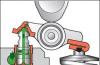
Hello, today I wanted to talk about such a malfunction as the knock of hydraulic lifters, ...

Founded in 1899 in Turin, FIAT is Italy's largest automaker. Under...

Motorists often face such a problem as a broken turn signal, but not ...
Because my car has already run a little more than 77 thousand km, and far from the best ...

Most of the VAZ-Chevrolet SUVs were and are produced with the 2123 engine. The most ...

