


amount installed sensors on modern car models often allows you to call them "computers on wheels". In order to tidy up the management of numerous electronic systems, a CAN bus was created. What it is and what are the principles of its work, we will consider in this article.
Historical reference
The first products in the automotive industry dispensed with electrical circuits at all. To start the car engine, a special magnetoelectric device was used that generates electricity from kinetic energy.
However, gradually the cars were more and more entangled with wires, and in 1970 they competed with airplanes in the degree of stuffing with various sensors. And the more instruments were placed in the car, the more obvious the need to rationalize the wiring circuits became.
The solution to the problem became possible with the microprocessor revolution and took place in several stages:
- In 1983, the German concern "Bosch" began to develop a new data transfer protocol for use in the automotive industry;
- Three years later, at a conference in Detroit, the protocol was formally introduced to the general public under the name Controller Area Network, or CAN for short;
- The practical implementation of the German invention was undertaken by Intel and Philips. The first prototypes date back to 1987;
- In 1988 bmw car The 8th series became the first machine to come off the assembly line, on which all sensors were organized according to the KAN technology;
- Three years later, Bosch updated the standard and added new features;
- In 1993, the KAN standard became international and received the ISO classifier;
- In 2001, every four-wheeled vehicle in Europe was mandatorily equipped with a CAN bus;
- In 2012, a new version of the bus was released: the speed of information transfer was increased, and compatibility with a number of new devices was organized.

CAN bus: how it works
The bus includes only a couple of wires connected to a single microchip. Each cable carries several hundred signals simultaneously to various controllers in the vehicle. Data transmission speed is comparable to broadband internet. In addition, if necessary, the signal will be amplified to the required level.
The technology can be broken down into several stages:
- Background mode - all nodes of the system are turned off, but power supply continues to the KAN-microchip. The energy consumption is extremely low at tiny fractions of a milliampere;
- Running - as soon as the driver turns the ignition key (or presses the “Start” button to start the engine - on some car models), the system literally “wakes up”. The mode of stabilization of the supply to the sensors is switched on;
- Active work - all controllers exchange the necessary (both diagnostic and current) information. Electricity consumption rises at peak loads to a record 85 milliamps;
- Falling asleep - as soon as the engine of the machine is turned off, the KAN sensors instantly stop working. Each of the system nodes independently disconnects from the electrical network and goes into sleep mode.

What is CAN bus in a car?
CAN in relation to the car can be called the "ridge" to which all electrical devices are connected. The signals are digital and the wires are connected in parallel to each controller. This achieves high network performance.
IN modern cars sensors from the following devices are combined into a single network:
- Motor;
- Gear box;
- Airbags (airbags);
- Anti-lock braking system;
- Power steering;
- Ignition;
- Dashboard;
- Tires (pressure controllers);
- Windshield wipers;
- Multimedia system;
- Navigation (GLONASS, GPS);
- On-board computer.

Application in other industries
The lightness and simplicity of the "CAN" technology reveal the possibilities of its application not only for "iron horses". The bus is also used in the following areas:
- Bicycle manufacturing. The Japanese brand Shimano announced in 2009 a bicycle with a CAN-based multilevel gearshift control system. The effectiveness of this step was so obvious that other firms, Marantz and Bayon-X, decided to follow in the footsteps of Shimano. The latter manufacturer uses a bus for a direct drive system;
- Known implementation of the so-called "smart home" on the principle of CAN-bus. Many devices that can solve certain tasks without the participation of people (automatic watering of grass on the lawn, thermostat, video surveillance system, lighting control, climate control, etc.) are combined into a single data transmission system. True, experts find the use of purely automotive technology in the human home rather dubious. Among weaknesses such a step is the absence of a unified international CAS standard for “smart homes”.

Advantages and disadvantages
"KAN-bus" is appreciated in mechanical engineering for such positive qualities:
- High-speed performance: the system is adapted to work in conditions of severe time pressure;
- Relative ease of integration into a machine and a low level of installation costs;
- Increased tolerance to interference;
- Multilevel control system that avoids many errors in the process of data exit-entry;
- The spread of working speeds allows you to adapt to almost any situation;
- Increased security level: blocking unauthorized access from outside;
- Variety of standards, as well as manufacturing companies. The range of tires available on the market allows you to find an option even for the cheapest car.
Despite the abundance of advantages, CAN technology is not devoid of a number of weaknesses:
- The amount of information that is available for simultaneous transmission in a "data packet" is quite limited for modern requirements;
- A significant part of the transmitted data has an overhead and technical purpose... The payload itself accounts for a tiny fraction of the network traffic;
- The upper layer protocol is not standardized at all.
Bosch has invented not only the spark plug and fuel filter, but also a kind of "Internet" for car sensors called CAN-bus. What is this standard in the field of linking together all controllers into a single neural network, became known about 30 years ago.

Video: how can-bus works in a car
In this video, mechanic Artur Kamalyan will tell you what the can-bus is used for in the car and how to connect to it:
Often the root cause of a malfunction is electronic system vehicle control - mechanical damage to the CAN bus or failure of control units hanging on the CAN bus.
Below in the article, you will find ways to diagnose the CAN bus with various faults. As an example, a typical CAN bus diagram is shown on a Valtra T "series tractor.
Legend:
- ICL - Instrumental Cluster
- TC1 / TC2 - Transmission controller (Transmission control unit 1/2)
- EC - Electronic controller
- PCU - Pump Control Unit
CAN BUS measurements
120 ohm terminating resistors (sometimes referred to as terminators) inside the EC control unit and a resistor located next to TC1
If the display (on the side pillar) shows a CAN-related DTC, then the CAN bus or control unit wiring is faulty.
The system can automatically report which of the control units cannot receive information (monitors of control units transmit information to each other).
If the display is flashing or the CAN bus message cannot be transmitted over the bus, a multimeter can be used to locate the fault in the CAN bus wiring (or faulty control unit).
CAN bus is not physically damaged
If the resistance between the Hi (High) and Lo (Low) wires of the CAN bus (at any point) is approximately 60 ohms, then the CAN bus is not physically damaged.
- The EC and TC1 control units are OK as the terminating resistors (120 Ohm) are located in the EC unit and next to the TC1 unit.
TC2 control unit and dashboard The ICLs are also intact as the CAN bus passes through these blocks.
CAN bus damaged

If the resistance between the Hi and Lo wires of the CAN bus (at any point) is approximately 120 ohms, then the CAN bus wiring is damaged (one or both wires).
CAN bus is physically damaged

If the CAN bus is damaged, locate the damage.
The resistance of the CAN-Lo wire is measured first, for example between the EC control units and TC2.
Therefore, measurements must be made between Lo-Lo or Hi-Hi connectors. If the resistance is approximately 0 ohms, then the wire between the measured points is not damaged.
If the resistance is approximately 240 ohms, then the bus is damaged between the measured points. The illustration shows a damaged CAN-Lo wire between the TC1 control unit and the ICL dashboard.
Short circuit in the CAN bus

If the resistance between the CAN-Hi and CAN-Lo wires is approximately 0 ohms, then a short circuit has occurred on the CAN bus.
Disconnect one of the control units and measure the resistance between the pins of the CAN-Hi and CAN-Lo connectors on the control unit. If the device works properly, reinstall it.
Then disconnect the next device and take measurements. Proceed in this way until a faulty device is found. The unit is faulty if the resistance is approximately 0 ohms.
If all units have been checked and the measurements are still signaling a short circuit, then the CAN bus wiring is faulty. To find the place of damage to the wires, they should be checked visually.
CAN bus voltage measurement

Turn on the power and measure the voltage between the CAN-Hi, CAN-Lo wires and the ground wire.
The voltage should be in the range of 2.4 - 2.7 V.
The CAN bus is one of the devices that makes it possible to more easily install the anti-theft system in a car. Knowing the features of the installation of the CAN module, you can make it yourself.
[Hide]
What is CAN bus and how it works
Automotive electronic KAN module is a network of controllers designed to integrate all control units of a car into one network. The main feature is that the combination of elements occurs using a single conductor. The digital interface itself on the car includes a pair of cables called CAN. The information that flows through the channels from one block to another is transmitted in encrypted form.
Where is the device
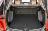
The location of the CAN bus depends on the specific car model, this point should be specified in the service manual for the car. It can be located in engine compartment or in the cabin, under the dashboard. The photo shows in detail examples of the location of the CAS interfaces.
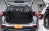
Kan module in one of the harnesses with standard wiring  Bus location in luggage compartment
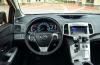
 CAN bus under car dashboard
Usually, the alarm control unit is placed under the control panel or behind the "tidy" in the passenger compartment.
Functions
Functions performed by the CAS interface:
- the ability to connect to the vehicle's electrical network and configure any devices, including car alarms;
- more simplified connection and operation algorithm additional equipment and systems installed in the car;
- the ability to simultaneously transmit and receive digital information and its analysis from various sources;
- reducing the impact of external interference on the operation of the main and additional systems;
- faster connection of the anti-theft system autostart function;
- accelerating the process of transferring data to specific devices and mechanisms of the machine.
Modes
The digital system can function in several modes:
- Standalone or background. When activated, all systems are turned off, but power is supplied to the KAN interface. The voltage value is quite low, so this operating mode will not allow the battery to discharge.
- Start mode. It works when the driver puts the key into the lock and scrolls it to the ignition position or clicks on. The power stabilization function is turned on. Voltage begins to flow to sensors and regulators.
- Active operating mode. When it is turned on, the exchange of information begins to occur between all sensors and regulators. When active mode is activated, the power consumption value may rise to 85 mA.
- Shutdown or sleep mode. When the motor stops, all sensors and systems connected to the CAN interface stop working. They are disconnected from the power supply of the machine.
Characteristics
Separately, it should be said about the main characteristics of the interface speed:
- the total rate of data transmission with information is 1 mb / s;
- when sending information between microprocessor devices this figure will be 500 kb / s;
- data acquisition speed to car system "Comfort" is 100 kb / s.
Varieties and device
According to the KAN device, the bus is a connector to which the units can be connected:
- signaling (with function automatic start or without it);
- powertrain control;
- anti-lock braking system operation;
- airbags;
- automatic transmission control;
- dashboards, etc.
According to the type of CAS identifiers used, the modules are divided into two classes:
- CAN2, 0A. This is a marking of interfaces that support the eleven-bit format of information exchange. This class of devices does not allow detecting errors for signals from 29-bit modules.
- CAN2, 0B. In this way, devices operating in eleven-bit format are marked. But their main feature is the ability to transfer error information to the microprocessor module when a 29-bit identifier is detected.
By type, digital interfaces are divided into several categories:
- For the car motor. When the interface is connected, fast communication is provided via the information transfer channel. The purpose of the device is to synchronize the operation of the microprocessor unit to other systems. For example, the engine and transmission.
- Comfort systems. The purpose of this type of device is to connect all systems that belong to this category.
- Information and command buses. The transfer rate is not very different. The purpose of the interface is to provide communication between systems to be served. For example, between a microprocessor module and a navigation device or mobile gadget.
Details on the methods of transferring information between devices via the KAN module are described in the video of the channel "Electrical Engineering and Electronics for Programmers".
Benefits of CAN bus signaling
Advantages typical for CAS interfaces:
- Ease of installation of additional equipment, for example, an anti-theft complex on a car. Thanks to the CAN bus, the car owner just needs to connect several connectors, and not connect wires to each individual system.
- Interface speed. The device allows for the rapid exchange of data between nodes and blocks.
- High resistance to external interference.
- All interfaces are characterized by a multi-level monitoring and control system. Its presence makes it possible to provide protection against errors that appear during the reception and transmission of information.
- During the operation of the CAS, the interface automatically spreads the speed over various channels. This ensures the efficient operation of the main units and systems connected to it.
- Increased system security. If necessary, the interface will be able to block illegal access that cybercriminals will try to get to the car anti-theft complex.
- Large selection of CAN modules. The consumer can choose a device for any vehicle model, even for a Zaporozhets.
You can learn more about the advantages of using CAN modules from the video filmed by the DIYorDIE channel.
Disadvantages of CAN bus signaling
Cons specific to these devices:
- The presence of restrictions in terms of the amount of transmitted information. Modern vehicles equipped with a variety of electronic devices and devices. As a result of an increase in their number, the load of the channel through which data is transmitted increases. This leads to increased response times.
- Most of the information that is transmitted through the interface has a specific purpose. Only a small portion of the redirected traffic is allocated to the payload on the bus.
- There may be problems in terms of lack of standardization. This is due to the use of a higher layer protocol.
How to install and connect the alarm to the CAN bus?
The presence of this interface allows you to connect the anti-theft complex with the "brains" of the car more quickly. You can do this task yourself.
Preparatory work
When preparing, you need to find out exactly where the microprocessor control module is located security system... If the installation procedure was carried out in garage conditions, then the search will not be difficult. In the case when the installation was carried out by specialists, it is necessary to clarify the location of the device.
Step-by-step instruction
The process of connecting the security complex to the KAN interface is performed as follows:
- The car alarm must be installed on the car and connected to all systems and components of the car.
- We need to find a thick wire with an orange edging. This conductor connects to the digital interface.
- The security complex module is connected to the specified contact. A connector is used for this.
- The microprocessor signaling unit is being installed in a safe and dry place. The device is fixed. It is necessary to insulate the joints of all conductors, as well as the cables themselves, to prevent chafing and damage to the insulation. After connecting, a check is performed.
- At the last stage, it is necessary to configure all the channels so that the security complex functions without interruption. The procedure for adjusting the parameters is carried out using the service manual that is included in the signaling package.
The user sigmax69 in the video showed how the procedure for connecting the anti-theft complex using the KAN module is performed using the example of a Hyundai Solaris car.
CAN bus faults
The following symptoms may indicate malfunctions in the CAS interface:
- several light indicators appeared on the control panel at the same time, indicating malfunctions;
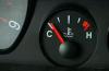
- there is no information on the tidy about the temperature of the coolant, the level of fuel in the tank, etc.;
- the Check Engine indicator appeared.
How to check?
If it is absent, you can use a multimeter:
- First you need to find the twisted pair wires of the interface. They are usually equipped with black or gray-orange insulation. The first option is high, the second is low.
- The tester is used to diagnose the voltage on the contacts, the ignition must be activated. Diagnostics should show a voltage value in the range from 0 to 11 volts, usually 4.5 V.
- Then the ignition in the car is turned off, the terminal clamp with the negative contact is disconnected from the battery.
- The resistance value between the cables is measured. If this parameter tends to zero, this indicates the presence of a short circuit in the interface. In the case when the voltage value moves to infinity, this indicates a break. Then a defect search is performed.
- A short circuit in the interface can occur as a result of the failure of one of the control modules. Then it is necessary to turn off each device in turn and re-measure the resistance.
How to fix it?
If the CAN bus is damaged, you need to find the broken contacts and repair them. The recovery procedure is performed by re-soldering. Damaged wires must also be replaced, as well as wires on which insulation has worn off.
Video "Car diagnostics using CAN bus"
The KV Avtoservice channel spoke in detail about the procedure for performing a computer check of the machine using the KAN interface.
The advent of digital buses in cars occurred later than they began to be widely implemented. electronic components... At that time, they only needed a digital "output" to "communicate" with diagnostic equipment - for this, low-speed serial interfaces like ISO 9141-2 (K-Line) were enough. However, the apparent complication of onboard electronics with the transition to CAN architecture has become its simplification.
Indeed, why have a separate speed sensor if the ABS unit already has information about the speed of rotation of each wheel? It is enough to transfer this information to the dashboard and to the engine control unit. For safety systems, this is even more important: for example, the airbag controller is already becoming able to independently turn off the engine in a collision by sending the appropriate command to the engine ECU, and de-energize the maximum on-board circuits by sending a command to the power control unit. Previously, it was necessary to use unreliable measures for safety, such as inertial switches and squibs at the battery terminal ( bMW owners with its "glitches" are already well known).
However, it was impossible to realize full-fledged "communication" of control units on the basis of the old principles. The amount of data and their importance increased by an order of magnitude, that is, a bus was required that is not only capable of operating at high speed and protected from interference, but also provides minimal transmission delays. For moving on high speed machines, even milliseconds, can already play a critical role. A solution to satisfy such demands already existed in the industry - we are talking about CAN BUS (Controller Area Network).
The essence of the CAN bus
Digital CAN bus is not a specific physical protocol. The principle of operation of the CAN bus, developed by Bosch in the eighties, allows it to be implemented with any type of transmission - even by wire, at least by fiber, at least by radio. KAN-bus works with hardware support for block priorities and the ability to "more important" interrupt the transfer of "less important".
For this, the concept of dominant and recessive bits has been introduced: in simple terms, the CAN protocol will allow any block to communicate at the right time, stopping data transmission from less important systems by simply transmitting a dominant bit while there is a recessive bit on the bus. This happens purely physically - for example, if the "plus" on the wire means "one" (dominant bit), and the absence of a signal means "zero" (recessive bit), then the transmission of "one" will definitely suppress the "zero".
Imagine a class at the beginning of a lesson. The students (low priority controllers) talk quietly with each other. But, as soon as the teacher (high priority controller) gives a loud command "Silence in the classroom!", Blocking out the noise in the classroom (the dominant bit suppressed the recessive one), the transfer of data between the student controllers stops. In contrast to the school class, this rule works on a permanent basis in the CAN bus.
What is it for? So that important data is transmitted with a minimum of delays, even at the cost of the fact that unimportant data will not be transferred to the bus (this distinguishes the CAN bus from the familiar Ethernet to everyone). In the event of an accident, the ability of the injection computer to receive information about this from the SRS controller is incomparably more important than the ability of the dashboard to receive the next data packet on the driving speed.
In modern cars, the physical distinction between low and high priorities has become the norm. They use two or even more physical buses of low and high speed - usually a "motor" CAN-bus and a "body" one, the data streams between them do not intersect. Only the CAN-bus controller is connected to all at once, which makes it possible to "communicate" with all units through one connector.
For example, Volkswagen technical documentation defines three types of CAN buses used:
- The "fast" tire, operating at a speed of 500 kilobits per second, integrates the engine, ABS, SRS and transmission control units.
- "Slow" operates at a speed of 100 kbit / s and combines the blocks of the "Comfort" system ( central locking, windows and so on).
- The third works at the same speed, but transfers information only between navigation, built-in phone, and so on. On older cars (eg Golf IV) the data bus and the comfort bus were physically combined.
Interesting fact: on Renault Logan the second generation and its "soplatformenniki" also physically have two buses, but the second one connects exclusively the multimedia system with a CAN controller, the second one contains the engine ECU, the ABS controller, the airbags, and the UCH.
Physically, cars with a CAN bus use it in the form of a twisted differential pair: in it, both wires serve to transmit a single signal, which is defined as the voltage difference on both wires. This is necessary for simple and reliable interference protection. An unshielded wire works like an antenna, that is, a source of radio interference is able to induce an electromotive force in it, sufficient for the interference to be perceived by the controllers as a really transmitted bit of information.
But in a twisted pair on both wires, the EMF value of the interference will be the same, so that the voltage difference will remain unchanged. Therefore, to find the CAN bus in the car, look for a twisted pair of wires - the main thing is not to confuse it with the wiring of the ABS sensors, which are also laid inside the car with a twisted pair to protect against interference.
They did not re-invent the CAN bus diagnostic connector: the wires were brought out to the free pins of the already standardized pads, in it the CAN bus is located on pins 6 (CAN-H) and 14 (CAN-L).

Since there can be several CAN buses on a car, it is often practiced to use different physical signal levels at each. Again, for an example, refer to the Volkswagen documentation. This is how the data transfer in the motor bus looks like:

When no data is transmitted on the bus or a recessive bit is transmitted, on both wires of the twisted pair the voltmeter will show 2.5 V relative to "ground" (the difference in signals is zero). At the moment of transmission of the dominant bit on the CAN-High wire, the voltage rises to 3.5 V, while on the CAN-Low it drops to one and a half. The difference is 2 volts and means "one".
Everything looks different on the Comfort bus:

Here "zero" is, on the contrary, a 5 volt difference, and the voltage on the Low wire is higher than on the High wire. A "unit" is a change in the voltage difference to 2.2 V.
Checking the CAN bus at the physical level is carried out using an oscilloscope, which allows you to see the real passage of signals through a twisted pair: it is naturally impossible to "see" the alternation of pulses of such length with a conventional tester.

"Decoding" of the vehicle CAN-bus is also carried out by a specialized device - an analyzer. It allows data packets to be output from the bus as they are transmitted.

You yourself understand that CAN bus diagnostics at the "amateur" level without the appropriate equipment and knowledge does not make sense, and it is simply impossible. The maximum that can be done by "improvised" means to check the kan-bus is to measure the voltage and resistance on the wires, comparing them with the reference ones for a particular car and a particular bus. This is important - we specifically gave an example above that even on the same car, there can be a serious difference between the tires.

Malfunctions
Although the CAN interface is well protected from interference, electrical problems have become a serious problem for it. The interconnection of the blocks into a single network made it vulnerable. The CAN-interface on cars has become a real nightmare for low-skilled auto electricians for one of its features: strong voltage surges (for example, winter) can not only "hang up" a detected CAN bus error, but also fill the memory of controllers with sporadic errors of a random nature.
As a result, a whole "garland" of indicators lights up on the dashboard. And while a newbie is scratching his head in shock: "but what is this?", A competent diagnostician will first of all put a normal battery.

Purely electrical problems are bus wire breaks, short circuits to ground or plus. The principle of differential transmission in case of breakage of any of the wires or "wrong" signal on it becomes unrealizable. The worst of all is the short circuit of the wire, because it "paralyzes" the entire bus.
Imagine a simple motor bus in the form of a wire on which several blocks "sit in a row" - the engine controller, the ABS controller, the dashboard and the diagnostic connector. A break at the connector is not terrible for the car - all units will continue to transmit information to each other in the normal mode, only diagnostics will become impossible. If we break the wire between the ABS controller and the panel, we will be able to see only it with the scanner on the bus, it will not show either the speed or the engine speed.
But if there is a break between the engine ECU and the ABS, the car will most likely not start: the unit, without "seeing" the controller it needs (information about the speed is taken into account when calculating the injection time and the ignition timing), will go into emergency mode.
If you do not cut the wires, but simply constantly apply “plus” or “ground” to one of them, the car will “go to the knockout”, since none of the blocks will be able to transmit data to the other. Therefore, the golden rule of an auto electrician, translated into Russian by the censor, sounds like "do not get crooked hands into the tire", and a number of car manufacturers prohibit connecting uncertified to the CAN bus additional devices third-party production (for example, alarm).
Fortunately, connecting the CAN-bus signaling not a connector to a connector, but cutting directly into the car's bus, gives the "curved" installer the opportunity to mix up the wires in places. After that, the car will not just refuse to start - if there is an onboard circuit control controller that distributes power, even the ignition is not a fact that it will turn on.
The electrical circuits of automobiles became more complex and expanded from year to year. The first cars dispensed with a generator and a battery - the ignition was powered by magneto, and the headlights were acetylene.
By the mid-70s, hundreds of meters of electrical wires were already tied into bundles, cars in terms of equipment with electrics competed with light-engine aircraft.
The idea of \u200b\u200bsimplifying the wiring lay on the surface - it would be nice to lay just one wire in the car, string consumers on it and put some kind of control device next to each. Then this wire could be used to send both energy for consumers (bulbs, sensors, actuators) and control signals.
By the beginning of the 90s, the development of digital technologies made it possible to start implementing this idea - the BOSCH and INTEL companies developed the CAN (Controller Area Network) network interface to create onboard real-time multiprocessor systems. In electronics, the wired system through which data is transmitted is called a “bus”.
If data is transmitted over two wires (so called "twisted pair") in series, pulse by pulse - it will be a serial bus, if data is transmitted over a bundle of several wires at the same time - it will be a parallel bus.
Although the parallel bus is faster, it is not suitable for simplifying the wiring of the car - it will only complicate it. A twisted-pair serial bus is capable of transmitting up to 1Mbps, which is sufficient.
The rules by which individual blocks exchange information are called in electronics a protocol. The protocol allows sending individual commands to individual blocks, polling each block individually or all at once. In addition to addressing devices, the protocol also provides for the ability to set priorities for the commands themselves. For example, a command to control the engine will override the command to control the air conditioner.
The development and miniaturization of electronics now allows the production of inexpensive control and communication modules that can be connected in a car in the form of a star, ring or chain.
The exchange of information goes in both directions, i.e. you can not only turn on, for example, a reversing light, but also get information if it shines.
Receiving information from various devices, the engine control system will select the optimal mode, the air conditioning system will turn on heating or cooling, the wiper control system will wave its brushes, etc.
The diagnostic system for the engine and the entire vehicle is also greatly simplified.
And although the electrician's main dream - only two wires throughout the car - has not yet come true, the CAN bus has significantly simplified the car's wiring and increased the overall reliability of the entire system.
So, CAN-bus is a digital communication and control system electrical devices car, which allows you to collect data from all devices, exchange information between them, manage them. Information about the state of devices and command (control) signals for them are transmitted in digital form using a special protocol with two wires, the so-called. "Twisted pair". In addition, power is supplied to each device from the on-board electrical network, but unlike conventional wiring, all consumers are connected in parallel, because there is no need to run a separate wire from each switch to each light bulb. This greatly simplifies installation, reduces the number of wires in bundles and increases the reliability of the entire electrical system.
You will also be interested in:
The new 2018-2019 Honda SRV crossover is definitely a great car. In our...
On June 15 in Russia, the official sales of Toyota Venza, a kind of cross between Camry and ...
So, you are the lucky owner of 1 million rubles. and you have a task to get yourself a good ...
The question of whether or not it is necessary to warm up a car engine in winter, in Russia ...

With age, even the purest oil, which has never overheated, tends to lose ...

