


The methods for diagnostics of the hydraulic system proposed in the article describe in sufficient detail and clearly the procedures for finding, identifying and eliminating malfunctions in the hydraulic system of an excavator and can serve as a practical guide for enterprises operating equipment with a hydraulic drive
Maintenance of hydraulic systems of machines should be carried out by highly qualified specialists using high-precision diagnostic devices that display information about problems on a computer. The latter should indicate methods of troubleshooting. This approach is increasingly being used.
However, even if there is no competent specialist nearby, and only simple measuring instruments are available from the diagnostic tools, it is possible to determine the causes of a hydraulic system malfunction quite accurately and quickly using a logical method of finding them. At the same time, it is necessary to understand well the basic principles of hydraulics and to know the basics of operation and structure of each element of the hydraulic drive.
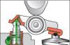
How do I stop the excavator?
Photo source: website
If a malfunction has resulted in the loss of functions of the machine, and / or adversely affects the safety of its operation, or damages the environment (for example, breaking the high pressure hose), the machine must be stopped immediately.
To ensure safety when stopping the machine, the following measures must be taken:
- lower all suspended working parts of the machine or fix them mechanically;
- relieve pressure in the entire hydraulic system;
- discharge all accumulators;
- relieve pressure from pressure transducers;
- turn off the electrical control system;
- disconnect the power supply.
It should be borne in mind that the working fluids used in hydraulic drives are low-compressible in comparison with gas and expand slightly when the pressure decreases. However, in those places of the hydraulic system where compressed gas can be located (due to insufficient deaeration or when a hydraulic accumulator is connected), the pressure should be reduced very carefully.
How to approach hydraulic system diagnostics?
Hydraulic system faults can be divided into two types:
- malfunctions that do not affect (of course, up to a certain time) on the functioning of the machine - functional malfunction in the hydraulic system (for example, increased leakage, temperature, etc.);
- faults affecting the function of the machine - a functional problem in the machine (for example, reduced performance).
The search for different types of faults is performed according to different algorithms.
There may be cases where the same malfunction (for example, of a pump) can lead to a functional malfunction in both the machine (reduced performance) and in the hydraulic system (increased noise level).
Experience has shown that it is preferable to start troubleshooting with the underlying problems and work through test procedures, taking into account such indications as temperature rise, noise, leaks, etc., as "clues". Common sense is critical, as certain symptoms can directly indicate a problem area. The jet of oil flowing out from under the hydraulic cylinder seal indicates where the problem area is.
 Photo source: website
However, some of the symptoms are not so obvious. If in any node there is a flow leakage during the transition from high pressure to low pressure, then local heat release occurs in it, which is not always possible to detect immediately.
Wherever you start your search, certain questions need to be answered before you can act. If there is a report of a problem, then it is necessary to collect as much factual information as possible. Perhaps this problem has already occurred and is recorded in the operating documents. In this case, you can save a lot of time. Check to see if any maintenance or adjustment work has been carried out on the system shortly before the malfunction occurs. It is necessary to determine the exact nature of the malfunction: it appeared suddenly or developed gradually, over a long time, on the operation of which parts of the machine it affects.
 Photo source: website
How to identify the simplest hydraulic system faults?
There are two ways to identify faults:
- with the help of the senses;
- using devices and tools.
The simplest faults in a hydraulic system can be detected with the help of the senses - by seeing, feeling, hearing - and very quickly. In practice, many problems are solved in this way, without the use of any tools.
| Heating the working fluid to a temperature of more than 60 ° С | On pipelines | - Low level working fluid in the tank - Clogged filters - Clogged breather |
| Heating pump | On the pump casing and adjacent units | - Low feed and, as a result, insufficient speed of working operations |
| Heating of hydraulic cylinders and hydraulic motors | On the body of the hydraulic cylinder, hydraulic motor and adjacent pipelines at a distance of 10-20 cm | - Defective hydraulic cylinder (wear of seals, damage to the piston) - Faulty hydraulic motor (wear of pistons and distributor, failure of bearings) |
| Heating of hydraulic valves | On the valve body and adjacent working fluid drain pipelines | - Defective hydraulic valve (wear of spools, faulty valves) |
If with the help of the senses it was not possible to identify the malfunction, then it is necessary to use devices: manometers, flow meters, etc.
How to approach the search for more complex hydraulic problems?
Before starting troubleshooting, you need to clearly know which parameters of the hydraulic system must be measured in order to obtain information about the location of the malfunction, and with what special tools, devices and equipment to do this.
Measured parameters
For the normal operation of the machine, a certain force (torque) must be transmitted to its working body at a certain speed and in a certain direction. The compliance of these parameters with the specified ones should be provided by the hydraulic drive, which converts the hydraulic energy of the fluid flow into the mechanical energy of the output link. The correct operation of the working body depends on the parameters of the flow - flow rate, pressure and direction.
Therefore, one or more of these parameters must be checked to test the hydraulic system. To make a decision on which parameters to check, it is necessary to obtain complete information about the malfunction.
Often the message about a malfunction in a car consists of rather inaccurate information, for example: "insufficient power". The power depends both on the effort on the output link and on its speed, i.e. from two parameters. In this case, more focused questions should be asked to decide which parameter to check: Is the drive running too slowly or is it not delivering the required force or torque?
 Photo source: website
After determining the nature of the malfunction (insufficient speed or force, wrong direction of movement of the working element), it is possible to determine the deviation of which flow parameter (flow rate, pressure, direction) from the required value led to this malfunction.
Although the troubleshooting procedure is based on monitoring flow, pressure and direction of flow, there are other system parameters that can be measured both to locate a faulty component and to determining the reasons for its malfunction:
- pressure at the inlet to the pump (vacuum) - for troubleshooting the suction lines;
- temperature - usually a higher temperature in one of the components of the system (compared to the temperature of the rest) is a sure sign that a leak is taking place;
- noise - With systematic and routine checks, noise is a good indicator of pump health.
- contamination level - in case of repeated occurrence of hydraulic system failures, the contamination of the working fluid should be checked to determine the causes of the malfunction.
 Photo source: website
Special devices, tools and equipment for hydraulic system diagnostics
In a hydraulic system, pressure is usually measured with a pressure gauge or vacuum gauge, and flow is measured with a flow meter. In addition, the diagnostician may benefit from other devices and tools:
- pressure transducer and recorder - if the accuracy of pressure measurement must be higher than the accuracy provided by the pressure gauge, as well as if it is necessary to measure pressure during a transient process or under the action of reactive disturbances from an external load (the pressure transducer produces an alternating voltage depending on the applied pressure);
- graduated vessel and stopwatch - when measuring very small flows, for example, leaks, they can be used to obtain greater accuracy than when measuring with a flow meter;
- temperature sensor or a thermometer - to measure the temperature in the hydraulic tank, you can install a temperature sensor (often combined with a working fluid level indicator), and it is recommended to use a sensor that gives an alarm as soon as the temperature of the working fluid becomes too low or too high;
- thermocouple - to measure the local temperature in the system;
- noise meter - increased noise is also a clear sign of system malfunction, especially for the pump. A noise meter can always be used to compare the noise level of a "suspect" pump with the noise level of a new pump;
- particle counter - allows you to determine the level of contamination of the working fluid with a high degree of reliability.
Diagnostics of the hydraulic system in the event of a functional malfunction in the excavator
Step 1. Wrong work drive may have the following reasons:
- the speed of the actuator does not match the specified one;
- the supply of the working fluid of the actuator does not correspond to the specified one;
- lack of movement of the actuator;
- movement in the wrong direction or uncontrolled movement of the actuator;
- incorrect sequence of switching on the actuators;
- "creep" mode, very slow operation of the actuator.
Step 2. According to the hydraulic diagram, the brand of each component of the system and its function are determined
Step 3. Make lists of nodes that may be the cause of the malfunction of the machine... For example, insufficient speed of the actuator of the drive may be the result of insufficient fluid flow entering the hydraulic cylinder, or its pressure. Therefore, it is necessary to compile a list of all the nodes that affect these parameters.
Step 4. Based on a certain diagnostic experience, the priority order of checking the nodes is determined.
Step 5. Each node in the list is pre-checked in order. The check is carried out according to such parameters as correct installation, tuning, signal perception, etc., in order to detect abnormal signs (such as elevated temperature, noise, vibration, etc.)
Step 6. If, as a result of a preliminary check, a faulty unit is not found, then a more intensive check of each unit is carried out using additional tools, without removing the unit from the machine.
Step 7. Verification using additional devices should help you find a faulty unit, after which you can decide whether it should be repaired or replaced.
Step 8. Before restarting the machine, it is necessary to analyze the causes and consequences of the malfunction.... If the problem is caused by dirt or an increase in the temperature of the hydraulic fluid, it may recur. Accordingly, it is necessary to take further measures to eliminate the malfunction. If the pump breaks down, then its debris could enter the system. Before connecting a new pump, the hydraulic system should be thoroughly flushed.
* Think about what could have caused the damage, as well as the further consequences of this damage.
Excavators are designed to work with frozen or not soils, as well as with pre-crushed rocks. The operating temperature range of the equipment is -40 ... + 40 ° С. The excavator device includes several units that ensure the operation of the machine.
How aggregates are classified
Excavators equipped with a working body with one bucket are divided into categories:
- By functional purpose. There are machines designed for construction work, special and career. The latter are equipped with a reinforced bucket designed for working with rocks.
- According to the design of the chassis - wheeled on a special chassis, wheeled on an automobile chassis, tracked. The latter can be equipped with extended track belts.
- By the type of drive of the working body - hydraulic, electric, combined.
How an excavator works
The general arrangement of an earth-moving excavator includes:
- undercarriage;
- engine;
- hydraulic system;
- transmission;
- a cabin with controls;
- platform with a rotating device;
- working boom.

An internal combustion engine with compression ignition is mounted on the turntable. The motor has a system liquid cooling... The cooling fans are driven automatically, but there is a forced switch button. To increase power and reduce fuel consumption, the installation of turbochargers is used. The engine drives the working mechanisms of the excavator through a hydraulic or electric transmission. Mechanical transmissions are used on outdated equipment.
The swivel part is mounted on the chassis through a shoulder strap that provides 360 ° rotation. The platform houses the operator's cab, hydraulic and electrical systems, boom with drive and control mechanisms. The excavator boom can be fitted with a variety of bucket designs or a trencher to reduce the time required to create trenches. It is possible to install hydraulic hammers or other equipment required for excavation work.
On excavators with a mechanical drive, winches are used that directly control the movement of the boom. On machines there are winches with 1 or 2 shafts. A 1-shaft unit is a unit in which the lifting and traction drums are mounted on a single shaft. If the drums of the winch are spaced along the shafts, then it is called 2-shaft. Similar mechanisms are installed on large excavators.
The winches are driven by shafts through a gearbox or by a chain from the main shaft of the transmission. Multi-disc friction clutches are used for switching on, band brakes for stopping. The rope is laid on the drum in one or more layers, depending on the length.
The design of a mini-excavator does not differ from the principles laid down in full-size equipment. The difference lies in the simplified design of the hydraulics and the use of a small diesel engine. The operator's workplace is located in a closed cabin equipped with ventilation and heating systems.

The loader excavator device is different from the above described mechanism. The work bucket is located on the articulated boom at the front of the standard wheeled tractor... The loading equipment has a hydraulic drive, which is controlled from the operator's cab.
480 RUB | UAH 150 | $ 7.5 ", MOUSEOFF, FGCOLOR," #FFFFCC ", BGCOLOR," # 393939 ");" onMouseOut \u003d "return nd ();"\u003e Dissertation - 480 rubles, delivery 10 minutes , around the clock, seven days a week
Melnikov Roman Vyacheslavovich. Improvement of methods for diagnosing hydraulic drives of road-building machines on the basis of studies of hydrodynamic processes in hydraulic systems: dissertation ... Candidate of technical sciences: 05.05.04 Norilsk, 2007 219 p. RSL OD, 61: 07-5 / 3223
Introduction
Chapter 1. Analysis of the existing maintenance system and the general state of the issue of the dynamics of the working fluid
1.1. The role and place of diagnostics in the system of maintenance of hydraulic drives SDM
1.2. General state of the issue of hydrodynamics of hydraulic drive SDM 17
1.3. Review of Research on Hydraulic Drive Dynamics
1.3.1. Theoretical research 24
1.3.2. Experimental studies 42
1.4. The use of electrohydraulic analogies in the study of wave processes in RZ in hydraulic systems SDM
1.5. Review of diagnostic methods for hydraulic drive SDM 52
1.6. Chapter Conclusions. Research goal and objectives 60
Chapter 2. Theoretical studies of hydrodynamic processes as applied to hydraulic systems SDM
2.1. Study of the propagation of the main harmonic along the hydraulic system of the SDM
2.1.1. Modeling the passage of the main harmonic through obstacles
2.1.2. General definition of the transfer function of a single-stroke double-acting hydraulic cylinder
2.1.3. Determination of pressure in the hydraulic line with oscillating excitation by solving the telegraph equation
2.1.4. Modeling wave propagation in hydraulic lines based on the method of electrohydraulic analogies
2.2. Assessment of the magnitude of the shock pressure in the hydraulic systems of construction machines using the example of the bulldozer DZ-171
2.3. Dynamics of the interaction of the pulsating RL flow and the pipeline walls
2.4. The relationship between oscillations of the walls of the hydraulic lines and the internal pressure of the working fluid
2.5. Chapter 103 Conclusions
Chapter 3. Experimental studies of hydrodynamic processes in hydraulic systems SDM
3.1. Justification of the experimental research methodology and the choice of variable parameters
3.1.1. General Provisions... The purpose and objectives of experimental research
3.1.2. Technique for processing experimental data and estimation of measurement errors
3.1.3. Determining the Regression Equation Type 106
3.1.4. Methodology and order of experimental research
3.2. Description of equipment and measuring instruments 106
3.2.1. Stand for research of wave processes in hydraulic systems
3.2.2. Vibration analyzer SD-12M 110
3.2.3. Vibration sensor AR-40 110
3.2.4. Digital tachometer / stroboscope "Aktakom" ATT-6002 111
3.2.5. Hydraulic press 111
3.3. Study of static deformation of high pressure hoses under load
3.3.1. Investigation of the radial deformation of RVD 113
3.3.2. Investigation of axial deformation of a high pressure hose with one free end
3.3.3. Determination of the form of the regression equation P \u003d 7 (Ds1) 121
3.4. On the question of the characteristics of the vibrations of the SDM in different areas of the spectrum
3.5. Study of the wave propagation speed and damping decrement of a single pulse in the MG-15-V liquid
3.6. Investigation of the nature of pressure pulsations in the hydraulic system of the EO-5126 excavator by vibrations of the walls of the hydraulic lines
3.7. Hydrodynamics of the working fluid in the hydraulic system of the DZ-171 bulldozer when lifting the blade
3.8. Study of the dependence of the amplitude of the main harmonic on the distance to the throttle slot
3.9. Conclusions on chapter 157
4.1. Selection of diagnostic parameter 159
4.3. Overflow criterion 165
4.4. Characteristics of analogues of the proposed method 169
4.5. Advantages and disadvantages of the proposed method 170
4.6. Specific Application Examples 171
4.7. Some technical aspects of the proposed diagnostic method
4.8. Calculation of the economic effect from the implementation of the proposed express method
4.9. Evaluation of the effectiveness of the implementation of the method of express diagnostics
4.11. Conclusions on chapter 182
Conclusions on work 183
Conclusion 184
Literature
Introduction to work
Relevance of the topic.The efficiency of maintenance of road construction machines (SDM) largely depends on the high-quality performance of technical diagnostics of the machine and its hydraulic drive, which is an integral part of most SDM. In recent years, in most sectors of the national economy, there is a transition to maintenance of road construction equipment according to the actual technical condition, allowing to exclude unnecessary repair operations Such a transition requires the development and implementation of new diagnostic methods for hydraulic drives SDM
Diagnostics of a hydraulic drive often requires assembly and disassembly work, which is associated with a significant amount of time. time, one of the sources of machine vibrations are hydrodynamic processes in hydraulic systems, and the vibration parameters can be used to judge the nature of the flowing hydrodynamic processes and the state of the hydraulic drive and its individual elements
By the beginning of the XXI century, the possibilities of vibration diagnostics of rotating equipment had grown so much that it formed the basis of measures for the transition to maintenance and repair of many types of equipment, for example, ventilation equipment, according to the actual state.However, for SDM hydraulic drives, the nomenclature of defects detected by vibration and the reliability of their identification is still insufficient to make such important decisions
In this regard, one of the most promising methods for diagnosing and hydraulic drives of SDM are methods of in-place vibration diagnostics based on the analysis of parameters of hydrodynamic processes
Thus, the improvement of methods for diagnosing hydraulic drives of road construction machines based on studies of hydrodynamic processes in hydraulic systems is actualscientific and technical problem
The purpose of the dissertation workconsists in the development of diagnostic methods for hydraulic drives SDM, based on the analysis of the parameters of hydrodynamic processes in hydraulic systems
To achieve this goal, it is necessary to solve the following tasks
Investigate the current state of the issue of hydrodynamics
hydraulic drive SDM and find out the need to take into account the hydrodynamic
processes for the development of new diagnostic methods
hydraulic drives SDM,
build and investigate mathematical models of hydrodynamic processes occurring in hydraulic systems of the SDM,
Experimentally investigate hydrodynamic processes,
flowing in hydraulic systems SDM,
Based on the results of the research conducted, develop
recommendations for improving diagnostic methods
hydraulic systems SDM,
Research object- hydrodynamic processes in hydraulic drive systems SDM
Research subject- regularities that establish links between the characteristics of hydrodynamic processes and methods for diagnosing hydraulic drives SDM
Research methods- analysis and generalization of existing experience, methods of mathematical statistics, applied statistics, mathematical analysis, method of electrohydraulic analogies, methods of the theory of equations of mathematical physics, experimental research on a specially created stand and on real cars
Scientific novelty of the results of the dissertation work:
A mathematical model of the passage of the first harmonic of pressure pulsations created by a volumetric pump (main harmonic) was compiled, and general solutions of the system of differential equations describing the propagation of the main harmonic along the hydraulic line were obtained,
Analytical dependencies for determining
internal fluid pressure in the RVD by deformation of it
multi-celled elastic shell,
The dependences of the deformation of the RVD on the internal
pressure,
Vibration spectra are experimentally obtained and investigated
elements of hydraulic lines in the HS of the EO-5126 excavator, D3-171 bulldozers,
self-propelled jib crane KATO-1200S in operating conditions,
a method for vibrodiagnostics of SDM hydraulic systems based on the analysis of the parameters of the fundamental harmonic of pressure pulsations generated by a positive displacement pump is proposed,
a criterion for the presence of a leakage in the hydraulic system of the SDM when using a new method of CIP technical diagnostics is proposed,
substantiated the possibility of using the parameters of hydraulic shocks arising as a result of a delay in the operation of safety valves for diagnostics of HS SDM
The practical significance of the results obtained.
a new method of vibration diagnostics for localizing faults in the elements of the hydraulic drive of the SDM is proposed,
a laboratory bench was created for the study of hydrodynamic processes in hydraulic systems,
The results of the work are used in the educational process in
lecture course, with coursework and diploma design, and
created laboratory facilities are used in carrying out
laboratory work
Privatecontribution applicant.The main results were obtained by the author personally, in particular, all analytical dependencies and methodological developments of experimental studies.When creating laboratory stands, the author proposed a general layout, calculated the main parameters and substantiated the characteristics of their main nodes and aggregates. practical implementation in operating conditions The author has personally developed programs and methods of experimental research, conducted research, processed and summarized their results, developed recommendations for the design of HS OGP taking into account wave processes
Approbation of work results.The results of the work were reported at the STC of the Norilsk Industrial Institute in 2004, 2005 and 2006, at the VIT All-Russian scientific and practical conference of students, postgraduates, doctoral students and young scientists "Science of the XXT century" MSTU in Maikop, at the scientific and practical conference "Mechanics - XXI century "BrSTU in Bratsk, at the 1st" All-Russian scientific and practical conference of students, graduate students and young scientists "in Omsk (SibADI), at the All-Russian scientific and practical conference" The role of mechanics in the creation of effective materials, structures and machines XXI
century "in Omsk (SibADI), as well as at scientific seminars of the Department of TMiO Research Institute in 2003, 2004, 2005 and 2006 Are brought to the defense -
scientific substantiation of a new method of express-diagnostics of hydraulic systems of SDM, based on the analysis of parameters of hydrodynamic processesat HS,
substantiation of the effectiveness of using the proposed method of CIP technical diagnostics,
Publications.Based on the results of the research, 12 printed works were published, including 2 articles in publications included in the list of the Higher Attestation Commission of the leading peer-reviewed journals and publications, an application was filed for a patent for an invention
Connection of the topic of work with scientific programs, plans and themes.
The topic is being developed within the framework of the proactive state budget topic "Improving the reliability of technological machines and equipment" in accordance with the plan of research work of the Norilsk Industrial Institute for 2004-2005, in which the author participated as a performer
Implementation of work.Operational tests of the express method for searching for leaks were carried out, the results of the work were accepted for implementation in the technological process at the enterprise MU "Avtokhozistvo", Norilsk, and are also used in the educational process at the State Educational Institution of Higher Professional Education "Norilsk Industrial Institute"
Work structure.The dissertation work consists of an introduction, four chapters fromconclusions, conclusions, a list of sources used, including 143 titles, and 12 annexes The work is presented on 219 pages, including 185 pages of the main text, contains 12 tables and 51 figures
The author considers it necessary to express gratitude to Melnikov VI, Candidate of Technical Sciences, Associate Professor of the Department of Technological Machines and Equipment (TMiO), GOUVPO Norilsk Industrial Institute (SRI), and Bashkirov BV, training master of the Department of TMiO SRI for help work
Main kept woman work
In the introductionsubstantiated the relevance of the dissertation topic, indicated the purpose of the work, formulated scientific novelty and practical value, provided a summary of the work and information about its approbation
In the first chapterthe modern system of maintenance of the SDM is considered, while it is indicated that an important place in the technological process of maintenance and repair is occupied by technical diagnostics, which are of two main types: general diagnostics (D-1) and in-depth diagnostics (D-2)
A comparative analysis of existing diagnostic methods was also carried out, while an acceptance was made on vibration methods One of the most frequently used methods in practice is the static-parameter method based on the analysis of parameters of a throttled flow of the working fluid This method is convenient in that it allows you to accurately identify the location of the fault, makes it possible when carrying out diagnostics, also adjust and run in the hydraulic system.At the same time, this method requires assembly and disassembly work, which leads to significant labor costs and leads to additional downtime Therefore, one of the directions for improving the MRO system is the development of CIP diagnostic methods, in particular, methods based on the analysis of the parameters of hydrodynamic processes in working fluids
However, at present, the defects detected by vibration diagnostics systems do not have quantitative characteristics similar to those of the structural parameters of the object.In particular, during vibration diagnostics, for example, the geometric dimensions of elements, the size of gaps, etc. are not determined. Quantitative estimates of the detected defects can considered a probabilistic assessment of the risk of an accident during the further operation of the equipment Therefore, the name of the detected defects often does not correspond to the names of those deviations of the element state from normal, which are monitored during the defect detection of equipment units. determining the effectiveness of vibration diagnostics systems
One of the most promising methods for modeling processes in hydraulic systems is the method of electrohydraulic analogies, in which each element of the hydraulic system is associated with a certain element of the electrical equivalent circuit
The general state of the issue of the hydrodynamics of the working fluid in volumetric hydraulic systems is investigated, and a review of works on this issue is carried out. It is determined that hydrodynamic processes have
significant impact on the performance of machines It is indicated that in a practical aspect, namely in the aspect of improving performance characteristics energy-intensive harmonics of large amplitude are important, therefore, when conducting research, it is advisable to focus attention, first of all, on them, that is, on harmonics of low frequency
Based on the research results, the goal and objectives of the research were formulated
In the second chapterthe results of theoretical studies of hydrodynamic processes in the RL are presented, the issue of the passage of waves through an obstacle is investigated, and on this basis the transfer functions for the passage of waves through some elements of hydraulic systems are obtained.In particular, the transfer function for some obstacle in the form of a gap in a pipe of constant cross section has the following form
4 - ( J>
w = ^-= -.
where and]- the amplitude of the incident wave, and 3 is the amplitude of the wave passing through the slit, to- the ratio of the cross-section of the pipe to the area of \u200b\u200bthe hole
For a double-acting single-stem hydraulic cylinder in the presence of overflow, the transfer function will have the form
1**" (2)
W =-
{1 +1 ") to " +1?
where t - the ratio of the area of \u200b\u200bthe piston to the area of \u200b\u200bthe rod, to -ratio of piston area to overflow area, U -the ratio of the effective cross-sectional area of \u200b\u200bthe hydraulic line to the piston area In this case, the internal diameters of the drain and pressure hydraulic lines are assumed to be equal to each other
Also in the second chapter, based on the method
electrohydraulic analogies modeling
propagation of a harmonic wave along a hydraulic line with distributed parameters Equations are known that describe rc and voltage in the line as a function of coordinates x nt
I th _ di
where R 0 is the longitudinal active resistance of a unit of line length, L 0 is the inductance of a unit of line length, Co is the capacitance of a unit of line length and G 0 is the transverse conductivity of a unit of line length. The equivalent circuit of an electric line is shown in Fig. 1
-1-G-E-
The well-known solution of system (3), expressed in terms of voltage and current at the beginning of the line, has the form
U= U, ch (yx) -/, Z Bsh (yx)
l \u003d I, c) i [) x) - ^ -, h () x)
V№ + y) labout)
constant spread,
\\ n + / wr ~ ~~wave impedance
Neglecting leaks, that is, assuming the hydraulic equivalent G 0 equal to іgul, we obtain equations for determining the harmonic function of pressure and flow rate at any point of the line, expressed in terms of pressure and flow rate at the beginning of the line
I Q \u003d P, ch (y lX) - Q- Sh (y rx)
Q- volumetric flow, 5 - pipe cross-section, R - pressure, p \u003d p e>-",
Q \u003d Q e" w+*>) , from- wave propagation speed, p 0 - density, and -
friction parameter, ω is the circular frequency of the wave After substitution of hydraulic analogs of electrical quantities into system (4), the solution of system (5) was obtained
I\u003e \u003d l \\ cf \\ x- ^ + ^- (-sinH + jcosH
- v \\ c \\ p,
V../ ,. 4l ", __ J / rt ..._," "J _".!,. 4 *. " (_ 5sh ^) + wso f)) | (8)
Є \u003d 0сй | * -4І + - (-sm (9) + v cos (i9))
Ї 1 + 4Ph (cos (0) - 7 smH) V o) pi
Taking into account the reflected wave, the pressure in the hydraulic line as a function of the coordinate and time takes the form
where R () H - the wave generated by the positive displacement pump, defined by expression (8), r -reflected wave
P ^ \u003d U, ") cP (g (l-x)) K 0 -Q (I, t) 7„Sh ( K (l-x)) K 0 (10)
where the reflection coefficient is determined by the expression r _ Zii-Zlb - Z „- hydraulic load resistance ~7 +7
The resulting model is valid not only for hydraulic lines with absolutely rigid walls of the hydraulic line, but also for high pressure hoses.In the latter case, the wave propagation speed should be calculated using the well-known formula
where r -radius of the hydraulic line, d -wall thickness, K -reduced bulk modulus of elasticity
The assessment of the maximum value of pressure overshoots in the event of hydraulic shocks in the hydraulic system of the DZ-171 bulldozer (basic machine T-170), arising from the stop of the hydraulic cylinders for lifting the blade, the resulting value was Ar, k 24.6 MI FaIn case of water hammer occurrence, in case of delay
actuation of safety valves for a time of 0.04 s, theoretically the maximum value of pressure overshoots in the hydraulic system of this machine is 83.3 MPa
Due to the fact that the measurements were supposed to be carried out on real machines by the CIP method, the question of the relationship between the amplitude of vibration displacements and vibration accelerations of the outer walls of pressure hydraulic lines and the amplitude of pressure pulsations in the hydraulic lines was considered.The resulting dependence for a rigid pipe has the form
dgf. ^ (D (p\u003e : -gCr. "і ^ + ^ -І
where x, -amplitude of vibration displacement of the pipe wall by i-Piiharmonics, E -young's modulus for the wall material, d -inner diameter of the hydraulic line, D- outer diameter of the hydraulic line, r" -fluid density, r st - density of the material of the walls of the hydraulic line, w, - frequency z harmonics.
V Vh / d H lr
H ^ 4 h
Figure 2 - Calculation scheme for determining the analytical dependence of the deformation of the metal braid of the RVD about g of the amplitude of the pulsations of the internal pressure
Similar dependency of multilayer metal braided flexible hose
reinforced (13)
where t - number of RVD braids, „ - number of strands in one section of one
braids, to and - depreciation coefficient of the outer lining, S! - area
the cross-section of one braid wire, and -the angle of inclination of the tangent to the plane perpendicular to the axis of the cylinder (Figure 2), x, -the value of the vibration displacement amplitude of the i-th harmonic, d -diameter of one braid wire, Do -reduced diameter of all RVD braids, S l -
value of the amplitude of the vibration velocity of the 7th harmonic at a frequency (o i, (r -angle of rotation of the radial ray connecting the point on the helical
lines and under 90 axis of the cylinder (sleeves), Have f- the volume of liquid contained inside the RVD in the contour of the wire area, V cm - volume of the part of the wall corresponding to the contour of the thread y \u003d d 8 U d D e 5 - wall thickness of the RVD,
th? Wed - the average diameter of the RVD, r f- fluid density
After solving equation 13 for the most common case, that is, with a \u003d 3516 ", and neglecting the inertial forces of the RVD walls in comparison with the elastic forces of the braids, a simplified dependence was obtained
d R = 1 , 62 Yu*^± X , ( 14 )
Doі
The third chapter presents the results of experimental studies
To substantiate the possibility of measuring the parameters of hydrodynamic processes in the RZ with the help of overhead sensors, a study was made of the dependence of the static deformation of the RVD on the internal pressure. RVD brand - B-29-40-25-4-U TU-38-005-111-1995, calculated for the nominal pressure Р nom \u003d 40 MPa RVD characteristic length - 1.6 m, inner diameter - 25 mm, outer diameter - 40 mm, the number of braids - 4, the diameter of the braid wire - 0.5 mm The radial and axial deformation of the high pressure hose was investigated when the pressure changed from 0 to 12 MPa
For RVD with both fixed ends, the dependence
radial deformation from pressure is shown in Fig. 3
that the RVD behaves differently with increasing pressure (the upper curve
in Fig. 3 a) and b)), and with a decrease in pressure (lower curve in Fig. 3 a) and
b)) Thus, the existence of the known phenomenon was confirmed
hysteresis during deformation of the RVD Work expended on deformation
for one cycle per one meter of the length of this RVD, turned out to be the same for
in both cases - 6.13 J / m It was also established that at large
pressures (\u003e 0.2P, IOVI), radial deformation remains practically
unchanged Such differentiation can probably be explained by the fact that
that in the section from 0 to 8 MPa the increase in diameter is due to
mainly by sampling the backlash between the layers of the metal braid, and
also by deformation of the non-metallic base of the hose.
circumstance means that at high pressures damping
the properties of the hydraulic line itself are insignificant, the parameters
hydrodynamic processes can be investigated by the parameters of the vibrations of the hydraulic line.It was found by the method of finite differences that the optimal regression equation describing the dependence P \u003d J.
The difficulty of toolless identification of a faulty assembly leads to increased maintenance and repair costs. When determining the reasons for the failure of any element of the system, it is necessary to carry out assembly and disassembly work.
Taking into account the latter circumstance, methods of CIP technical diagnostics are highly effective. In connection with the rapid development of computer technology in recent years, the reduction in the cost of hardware and software for digital measuring instruments, including vibration analyzers, a promising direction is the development of methods for CIP vibration diagnostics of hydraulic drives SDM, based, in particular, on the analysis of hydrodynamic processes in horizontal wells.
General definition of the transfer function of a single-stroke double-acting hydraulic cylinder
The pressure pulsations created by the OH in the hydraulic system of the SDM can be decomposed into harmonic components (harmonics). In this case, the very first harmonic has, as a rule, the largest amplitude. We will call the first harmonic of pressure pulsations created by OH, the main harmonic (GT).
In the general case, the construction of a mathematical model for the propagation of the main harmonic along the pressure hydraulic line from the source (pump) to the working element is a laborious task that must be solved for each hydraulic system separately. At the same time, the transfer functions for each link of the hydraulic system (sections of hydraulic lines, hydraulic devices, valves, local resistances, etc.), as well as feedbacks between these elements, must be determined. The presence of feedback can be said if the wave propagating from the source interacts with the wave propagating towards the source. In other words, feedback occurs when interference occurs in the hydraulic system. Thus, the transfer functions of the elements of the hydraulic system should be determined not only depending on design features hydraulic drive, but also depending on the modes of its operation.
The following algorithm is proposed for constructing a mathematical model of the propagation of the main harmonic along the hydraulic system:
1. In accordance with the hydraulic diagram, as well as taking into account the operating modes of the hydraulic system, a structural diagram of the mathematical model is drawn up.
2. Based on the kinematic parameters of the HM, the presence of feedbacks is determined, after which the structural diagram of the mathematical model is corrected.
3. The choice of the optimal methods for calculating the main harmonic and its amplitudes at various points of the HM is made.
4. The gear ratios of all links of the hydraulic system are determined, as well as the gear ratios of feedbacks in operator, symbolic or differential form, based on the previously selected calculation methods.
5. The calculation of the parameters of the HS at the required points of the HS.
It should be noted several regularities of the mathematical models of the passage of the GG through the hydraulic systems of the SDM.
1. The law of propagation of the main harmonic in the most general case does not depend on the presence (absence) of branches from the hydraulic line. The exceptions are cases when the length of the branches is a multiple of a quarter of the wavelength, that is, those cases when the necessary condition for the occurrence of interference is satisfied.
2. Feedback depends on the operating mode of the hydraulic drive, and can be either positive or negative. A positive one is observed when resonance modes appear in the hydraulic system, and a negative one is observed when antiresonant modes arise. Due to the fact that the transfer functions depend on a large number of factors and can change when the operating mode of the hydraulic system changes, it is more convenient to express positive or negative feedback (in contrast to automatic control systems) as a plus or minus sign in front of the transfer function.
3. The investigated harmonic can serve as a factor initiating the emergence of a number of secondary harmonic components.
4. The proposed method for constructing a mathematical model can be used not only in studying the law of propagation of the main harmonic, but also in studying the law of behavior of other harmonics. However, due to the above circumstances, the transfer functions for each frequency will be different. As an example, let us consider the mathematical model of the propagation of the main harmonic along the hydraulic system of the DZ-171 bulldozer (Appendix 5). D2
Here L is a source of pulsations (pump); Dl, D2 - vibration sensors; Wj (p) -transfer function of the hydraulic line in the section from the pump to the OK; \\ Uz (p) -transfer function OK; W2 (p) - transfer function for the wave reflected from the OC and propagating back to the pump; W4 (p) -transfer function of the section of the hydraulic line between the OC and the distributor; Ws (p) - distributor transfer function; W7 (p) and W8 (p) - transfer functions of waves reflected from the distributor; W6 (p) - transfer function of the section of the hydraulic line between the distributor and hydraulic cylinders 2; W p) - the transfer function of the hydraulic cylinder; Wn (p) - transfer function of the hydraulic line in the section from the distributor to the filter; Wi2 (p) - filter transfer function; Wi3 (p) is the transfer function of the hydraulic system for the wave reflected from the piston of the hydraulic cylinder.
It should be noted that for a serviceable hydraulic cylinder, the transfer function is equal to 0 (the wave does not pass through the hydraulic cylinder in the absence of leaks). Based on the assumption that overflows in hydraulic cylinders are usually small, then feedback between the filter, on the one hand, and the pump, on the other, we neglect. Modeling the passage of the main harmonic through obstacles Consideration of the passage of a wave through an obstacle is generally a physical problem. However, in our case, on the basis of physical equations, the process of wave propagation through some elements of hydraulic systems will be considered.
Consider a hydraulic line with a cross-sectional area Si, having a solid obstacle with an opening with an area S2 and a width br. First, let us define in general terms the ratio of the amplitudes of the incident wave in the hydraulic line 1 (tfj) to the amplitude of the wave that passed through the slot 2 (Fig. 2.1.2). Line 1 contains the incident and reflected waves:
General Provisions. The purpose and objectives of experimental research
The data obtained in the second chapter made it possible to formulate the tasks of experimental research in the third chapter. The purpose of the experimental research: "Obtaining experimental data on hydrodynamic processes in the fluid in the hydraulic systems of the SDM" The objectives of the experimental studies were: - to study the properties of the high pressure hoses in order to study the adequacy of the measured parameters of the oscillations of the outer walls of the high pressure hoses to the parameters of the hydrodynamic processes in the hydro systems of the SDM; - determination of the decrement of attenuation of waves in the RZ used in the hydraulic systems of the SDM; - study of the spectral composition of pressure pulsations in SDM hydraulic systems containing gear and axial piston pumps; - study of the properties of shock waves arising in the hydraulic systems of the SDM during the operation of machines; - study of the patterns of wave propagation in the RZ.
The calculation of the errors of the measured values \u200b\u200bwas carried out using statistical methods. The approximation of dependences was carried out by the method of regression analysis based on the method of least squares, under the assumption that the distribution of random errors is normal (Gaussian). The calculation of measurement errors was carried out according to the following relations: cj \u003d jo2s + c2R, (3.1.2.1) where the systematic error JS was calculated according to the following dependence: r \u003d r1 gl + r2o (3.1.2.2), and the random error aA is from the theory of small samples. In the above formula and A is the instrument error; m0 is a random error. Checking the correspondence of the experimental distribution to the normal one was carried out using the Pearson's goodness-of-fit test: , where and ,. \u003d - (p (ut) theoretical frequencies, n \\; are empirical frequencies; p (u) \u003d - \u003d e and 2 \\ n is the sample size, h is the step (the difference between two adjacent n / 2r options), ab is the mean square deviation, and, \u003d - To confirm the compliance of the studied samples with the normal distribution law, the “W test” was used, which is applicable for small samples.
According to one of the corollaries of Taylor's theorem, any function that is continuous and differentiable on a certain section can, with some error, be represented on this section as a polynomial nth degree... The order of the polynomial n for experimental functions can be determined by the method of finite differences [b].
The tasks of experimental studies, indicated at the beginning of the section, were solved in the same sequence. For greater convenience, the methodology, procedure, and results obtained will be presented for each experiment separately. Here, we note that tests on real machines were carried out in a garage, that is, the equipment was in a closed room, the ambient temperature was + 12-15C, and before the measurements began, the pumps of the machines were idling for 10 minutes. The force with which the piezoelectric sensor pressed against the hydraulic line is -20N. The center of the sensor touched the hose in all measurements taken on the hose.
A necessary condition for the study of wave processes is empirical research on special laboratory stands and installations. In the field of oscillatory processes of hydraulic systems, complex systems with positive displacement pumps and hydraulic lines with distributed parameters are currently insufficiently studied.
To study these processes, a laboratory setup was developed and manufactured, shown in Fig. 3.1.
The unit consists of a vertical frame (1) installed on a stable base (2), a tank (3), a gear motor-pump BD-4310 (USA) (4), a safety valve (5), a suction (6) and pressure (7) lines, acceleration section (8), hydraulic shock absorber (9), control-load valve (throttle) (10), drain line (11), pressure sensor (12), pressure gauge (13), autotransformer (14), step-down transformer (15).
The adjustable parameters of the stand are: the length of the booster section, the speed of the electric motor and the drive shaft of the gear pump, the stiffness of the hydraulic shock absorber, the pressure drop across the load control valve, and the setting of the safety valve.
The measuring instruments of the stand are a pressure gauge (13), which records the pressure in the pressure line, a high-frequency strain gauge of pressure at the accelerating section, a CD-12M vibration analyzer, and a tachometer for measuring the speed of the electric motor shaft.
In addition, during the experiments, an oil change is provided, with the measurement of its parameters (in particular viscosity), as well as a change in the rigidity of the walls of the hydraulic lines of the accelerating section. There is a variant of incorporating bellows-type concentrated elasticity into the hydraulic circuit with the possibility of adjusting its natural vibration frequency using replaceable weights. Internal diameter of rigid hydraulic lines - 7 mm. The material of the hydraulic lines is steel 20.
The adjustment range of the stand in combination with replaceable equipment makes it possible to study resonant and antiresonant processes in a pressure hydraulic line, to determine the reduced reflection coefficients of waves from a pneumatic hydraulic shock absorber (9). Alternatively, a change in the temperature of the working fluid is provided to study its effect on the viscosity, elasticity and wave propagation speed.
The stand is made according to the block-modular scheme. The vertical part of the frame is designed with longitudinal guides, on which, on both sides, various components and assemblies of the hydraulic system under study can be mounted along the entire length. In particular, the installation of a bellows-type resonator is provided, which is connected to the control throttle and the drain line with a flexible high-pressure hose with a metal braid. In the longitudinal grooves of the lower part of the frame, the installation of various injection and control equipment is provided.
Recommendations for the implementation of the diagnostic method in the technological process
In addition to the spectral composition of the RL vibrations, and as a consequence, the vibrations of the walls of the hydraulic lines, it is of interest to measure the general level of vibrations. To study the hydrodynamic processes occurring in the hydraulic systems of the SDM, in particular, in the hydraulic systems of bulldozers based on the T-170M tractor, the total vibration level at the control points was measured.
The measurements were carried out with an AR-40 vibration accelerometer, the signal from which was fed to the input by an SD-12M vibration analyzer. The sensor was attached to the outer surface of the hydraulic line wall using a metal bracket.
When measuring the total level (OU), it was noticed that at the end of the process of raising or lowering the blade (at the time of stopping the hydraulic cylinders), the amplitude of oscillations (PIK) of the vibration accelerations of the hydraulic line wall increases sharply. This can be partially explained by the fact that at the moment the blade hits the ground, as well as at the moment the hydraulic cylinders stop when the blade is raised, vibration is transmitted to the bulldozer as a whole, including the walls of the hydraulic line.
However, one of the factors affecting the magnitude of the vibration acceleration of the walls of the hydraulic line may also be a water hammer. When the dozer blade, when lifting, reaches the uppermost position (or, when lowering, it stops on the ground), the hydraulic cylinder rod with the piston also stops. The working fluid moving in the hydraulic line, as well as in the rod cavity of the hydraulic cylinder (working to lift the blade), encounters an obstacle in its path, the inertial forces of the fluid pressure on the piston, the pressure in the rod cavity increases sharply, which leads to a water hammer. In addition, from the moment when the piston of the hydraulic cylinder has already stopped, and until the moment when the liquid through the safety valve goes to drain (until the safety valve is triggered), the pump continues to pump liquid into the working cavity, which also leads to an increase in pressure.
During the research, it was determined that the amplitude of the vibration accelerations of the pressure hydraulic line wall increases sharply both in the area directly adjacent to the pump (at a distance of about 30 cm from the latter) and in the area directly adjacent to the hydraulic cylinder. At the same time, the amplitude of vibration accelerations at the control points on the body of the bulldozer increased insignificantly. The measurements were carried out as follows. The bulldozer based on the T170M tractor was on a flat concrete floor. The sensor was sequentially fixed at control points: 1 - point on the pressure hydraulic line (flexible hydraulic line), directly adjacent to the pump; 2 - point on the pump casing (on the union), located at a distance of 30 cm from point 1.
Measurements of the PIK parameter were carried out in the process of lifting the dump, and the first two or three averaging were performed in the state idle work pump, that is, when the blade lift cylinder was at rest. When the blade was raised, the value of the PIK parameter began to increase. When the dump reached the extreme upper position, the PIK parameter reached its maximum (RR / T-maximum). After that, the dump was fixed in the extreme upper position, the PIK parameter dropped to the value it had at the beginning of the lifting process, that is, when the pump was idling (TJ / G-minimum). The interval between adjacent measurements was 2.3 s.
When measuring the PIK parameter at point 1 in the range from 5 to 500 Hz (Fig. 3.7.2) based on a sample of six measurements, the arithmetic mean ratio of the PIK maximum to the RN / G-minimum (PIKshks / PIKmt) is 2.07. When the standard deviation of the results is o \u003d 0.15.
From the data obtained, it can be seen that the kv coefficient is 1.83 times greater for point 1 than for point 2. Since points 1 and 2 are located at a small distance from each other, and point 2 is more rigidly connected to the pump casing than point 1, then you can assert: the vibrations at point 1 are largely due to pressure pulsations in the working fluid. And the maximum vibration at point 1, created at the moment the blade stops, is caused by a shock wave propagating from the hydraulic cylinder to the pump. If the vibration at points 1 and 2 was due to mechanical vibrations that occur at the time the blade stopped, then the vibration at point 2 would be greater.
Similar results were obtained when measuring the VCI parameter in the frequency range from 10 to 1000 Hz.
In addition, when conducting research on the section of the pressure hydraulic line immediately adjacent to the hydraulic cylinder, it was determined that the general level of vibrations of the hydraulic line wall is much higher than the general level of vibrations at the control points on the body of the bulldozer, located, for example, at a short distance from the attachment point of the hydraulic cylinder.
To prevent the occurrence of a water hammer, it is recommended to install damping devices in the section of the hydraulic line directly connected to the hydraulic cylinder, since the process of propagation of the hydraulic shock begins precisely from the working cavity of the latter, and then the shock wave propagates throughout the hydraulic system, which can lead to damage to its elements. Figure: 3.7.2. The general level of vibration at control point 1 (PIK-5-500 Hz) Fig. 3.7.3. General level of vibrations at control point 2 (pump nozzle) (PIK-5 - 500 Hz) Timing diagrams of pulsations of the outer surface of the pressure line wall in the process of lifting the blade of the DZ-171 bulldozer
A significant amount of information about dynamic processes in the working fluid can be obtained by measuring the parameters of its pulsations in real time. The measurements were taken while raising the dozer blade from rest to the uppermost position. Figure 3.7.4 shows a graph of the change in the vibration acceleration of the outer surface of the wall of the pressure line section, directly adjacent to the NSh-100 pump, depending on time. The initial section of the graph (0 t 3 s) corresponds to the idling of the pump. At the moment of time t \u003d 3 s, the bulldozer operator switched the distributor handle to the "lift" position. At this moment, a sharp increase in the amplitude of vibration accelerations of the hydraulic line wall followed. Moreover, not a single pulse of large amplitude was observed, but a cycle of such pulses. Of the 32 vibrograms obtained (on 10 different bulldozers of the specified brand), there were mainly 3 pulses of different amplitudes (the largest amplitude was in the second one). The interval between the first and second impulses was shorter in duration than the interval between the second and third (0.015 s versus 0.026), that is, the total pulse duration is 0.041 s. On the graph, these impulses merge into one, since the time between two adjacent impulses is rather short. The average amplitude of the maximum value of vibration acceleration increased on average by k \u003d 10.23 times as compared to the average value of vibration acceleration during the idling of the pump. The root-mean-square error was st \u003d 1.64. On similar graphs obtained when measuring the vibration accelerations of the pump nozzle wall connecting the high-pressure cavity of the latter with the pressure line, such a sharp jump in vibration accelerations is not observed (Fig. 3.7.4), which can be explained by the stiffness of the nozzle walls.
Kosolapov, Victor Borisovich
Hydraulic excavator class 330-3
write [email protected]website
call 8 929 5051717
8 926 5051717
Brief introduction:
Measure the setting pressure of the main safety valve in the discharge port of the main pump (The setting pressure of the main safety valve can also be measured using the Dr.ZX diagnostic system.)
Training:
1. Turn off the engine.
2. Press down on the air release valve located on the top of the hydraulic tank to relieve any residual pressure.
3. Remove the main pump discharge port plug. Install the adapter (ST 6069), hose (ST 6943) and pressure gauge (ST 6941).
: 6 mm
Connect the Dr.ZX diagnostic system and select the monitor function.
4. Start the engine. Make sure there is no visible leakage at the place where the pressure gauge is installed.
5. Maintain the temperature of the working fluid within 50 ± 5 ° C.
Taking a measurement:
1. The measurement conditions are shown in the table below:
2. First, slowly move the bucket, arm, and boom control levers to full travel and relieve each circuit.
3. Regarding the rotation function of the turntable, keep it stationary. Relieve the turntable rotation circuit by slowly moving the travel control lever.
4. Regarding the travel function, secure the tracks against a stationary object. Slowly move the travel control lever to relieve the travel contour.
5. While pressing the Dig Mode Power Switch, slowly move the bucket, stick and boom control levers to full speed and relieve each circuit for eight seconds.
Evaluation of results:
Refer to the topic "Standard Performance" in subsection T4-2.
NOTE: If the measured pressure values \u200b\u200bfor all functions are lower than the specifications, probable cause the setting pressure of the main safety valve may be too low. If the opening pressure is lower than the required value for only one function, the main safety valve may not be the cause.
Main Relief Valve Setting Pressure Adjustment Procedure
Adjustment:
When adjusting the setting pressure during a high power dig operation, adjust the setting pressure on the high side of the main relief valve. If adjusting the setting pressure during digging operation at normal power mode, adjust the setting pressure from the low pressure side of the main relief valve.
- High Side Main Relief Valve Setting Pressure Adjustment Procedure
1. Loosen the lock nut (1). Tighten the plug (3) slightly until the end of the plug (3) touches the end of the piston (2). Tighten the lock nut (1).
: 27 mm
: Plug (3): 19.5 Nm (2 kgfm), Lock nut (1): 68 ... 78 Nm (7 ...
8 kgf m) or less
2. Loosen the lock nut (4). By turning the plug (5), adjust the set pressure according to the specification data.
: 27 mm, 32 mm
: Lock nut (4): 78 ... 88 Nm (8 ... 9 kgfm) or less
- Low Side Main Relief Valve Setting Pressure Adjustment Procedure
1. Loosen the lock nut (1). Turn the plug (3) counterclockwise until the set pressure is as specified. Tighten the lock nut (1).
: 27 mm, 32 mm
: Lock nut (1): 59 ... 68 Nm (6 ... 7 kgfm) or less
2. After finishing the adjustment, check the set pressure values.
NOTE: Typical Set Pressure Changes (Reference Values)
| Screw speed | 1/4 | 1/2 | 3/4 | 1 | |
| Relief valve pressure change value: Plug (5) (high pressure side) | MPa | 7,1 | 14,2 | 21,3 | 28,4 |
| (kgf / cm2) | 72,5 | 145 | 217,5 | 290 | |
| Safety valve pressure change value: Plug (3) (low pressure side) | MPa | 5,3 | 10,7 | 16 | 21,3 |
| (kgf / cm2) | 54 | 109 | 163 | 217 | |
We provide consultations upon request and provide free technical support and consultations
write [email protected]website
call 8 929 5051717
Hydraulic excavators have a very wide range of applications
- Compared to other machines such as a bulldozer or a loader, an excavator can do a wide range of jobs from one point;
- The ability to swivel at 3600 allows the excavator to easily work in confined spaces;
- High dripping power allows the excavator to gently drip, dig trenches and form bases;
- Since the work takes place practically without moving the machine, the wear of the running gear is minimal;
- Easy change of working equipment allows you to use the excavator for a variety of tasks.
Using
- Moving soil
- Planning
- Loosening
- Loading
- Layout
The working equipment of an excavator looks like a human hand and performs a similar function.

When replacing the bucket with other attachments, you can perform other miscellaneous work such as grabbing or chiselling
Excavator classification
Today, crawler excavators are mainly used because of their large footprint and high stability.
Advantages of tracked excavators
- High stability
- Ability to work on soft and uneven ground
Large footprint provides greater stability. This makes it easy to work on soft or uneven ground
Disadvantages of crawler excavators
- Slow travel speed and mobility
- Damage to the road surface
Low transport speed. If the machine is equipped with steel tracks, the road surface will be damaged while driving.
The excavator can be divided into 3 parts: work equipment, top and bottom
The upper part is based on the turntable frame


The turning system consists of:
- Swing motor (turns the platform)
- Swing gear (increases motor force and reduces swing speed)
- Turntable (connects platform to crawler cart)
- Center pivot link (transfers oil flow to bottom)
The turntable consists of two rings, one outer and one inner. The inner ring is firmly attached to the crawler frame and the outer ring is firmly attached to the turntable frame. The turntable is the link that transfers the load of the turntable with the implement to the undercarriage for stability.

The swivel link consists of a housing (stator) and a rotor
The rotor is attached to the track unit. The body is attached to the turntable and rotates with it

The oil from the control valve enters the link housing and flows through the annular channels into the rotor channels. Leaving the channels of the rotor through the hoses, the oil gets to the hydraulic motors.

The lower part consists of many different elements that are attached to a steel frame called the crawler frame

Excavator Hydraulic Power Line
During work, the operator can simultaneously perform several operations, such as moving the boom, stick, bucket, turning at the same time. In this case, several sections of the control valve operate simultaneously.
The undercarriage of a hydraulic excavator is significantly different from a bulldozer or loader, in which power is transmitted mechanically using a torque converter and gears
Just like the heart pumps blood, the excavator's hydraulic pump pumps oil for the hydraulic cylinders

To push out the handle, oil must be fed into the stem cavity

To fold the handle, oil must be fed into a rodless cavity

Main overflow valve
The main overflow valve keeps the pressure below a certain value by overflowing excess oil into the tank. When, during movement, the piston reaches the edge of the cylinder, it stops. As the oil continues to flow, the pressure in the system begins to build up, causing the hoses to burst. The main overflow valve in the system prevents pressure build-up to a critical level by overflowing the oil into the tank. The main overflow valve is located between the check valve and the hydraulic pump.
Safety valve
The safety valve serves to discharge oil into the tank if the pressure in the system exceeds the critical value. If a piece of rock falls on the boom and the control valve is in the neutral position, the pressure in the cylinder will immediately increase and cause the hoses to burst. To prevent the pressure from rising above a certain level, a safety valve is installed in the system. This valve is located after the control valve in front of the hydraulic cylinders.
Classification of hydraulic pumps
Comparison of piston and gear hydraulic pumps
Model number
PC 200 XX - 7, where
PC - Product Code.
200 - Size Code [Number, approximately 10 times the operating weight (in tonnes), but sometimes the number of the machine related to this model is displayed]
XX - Sub Model Code [Identified by one or two letters LC: Long Base]
7 - Modification [Displays the history of the model (numbers 4, 9 and 13 are missing)]
Classification of hydraulic excavators by size
Small: less than 20 tons
Medium: 20-59 tone
Severe: 60 or more
Bucket capacity
Heaped Capacity \u003d Geometric Capacity + Heaped Volume

Bucket Standards
Angle of repose 1: 1

Angle of repose 1: 2

ISO: International Organization for ISO7451 and ISO7546
JIS: Japanese Industrial Standard JIS A8401-1976
PCSA: Crane and Excavator Association (USA) PCSA No.37-26
SAE: Association of Auto Engineers (USA) SAE J296 / J742b
CECE: European Society for Building Technology CECE SECTION V1
Ground pressure
Ground pressure (kg / m 2) \u003d Excavator weight / Ground area

The ground pressure of a middle class excavator is not much greater than the ground pressure of a standing person
If a person can walk on the ground, then a middle class excavator can work there.
Example of using work equipment
1. Soft ground (wide shoes)
For work on soft ground, such as swampy ground, wide shoes are used to reduce ground pressure
2. Offset boom
If the machine does not stand in the center of the excavated object due to various obstacles on the sides, work is carried out with an excavator with a displaceable stick. This method is used for digging trenches (the offset stick does not change the direction of the digging axis, but shifts it to the side relative to the center of the machine)
3. Long range (extra long equipment)
When used with extra-long attachments, it allows work to be carried out in places where the machine cannot work with conventional attachments. Deepening of rivers, swamps, etc. Long slopes can also be graded
4. Grading of slopes (leveling bucket)
Grading of river slopes, roads and other objects can be easily done with a special flat-bottomed bucket.
5. Crushing (hydraulic hammer)
By using a hydraulic hammer, large rock debris after blasting can be crushed. You can also demolish concrete roads and buildings
6. Disposal of vehicles (hydraulic shears)
By using special hydraulic shears, vehicles can be disassembled into parts. These units can grab small pieces and sort the pieces for recycling.
7. Demolition of buildings (shears and hydraulic breakers)
The machine is equipped with extra-long working equipment and can carry out demolition work. With the shears, you can also cut the steel frame and structural members.
8. Logging (saws and grabs)
Excavators are used for procurement work. Grips with saws can take everything, including fallen trees, remove branches and sawed logs. Grips are used for loading operations.
History of hydraulic excavators
You will also be interested in:
Hello, today I wanted to talk about such a malfunction as the knock of hydraulic lifters, ...

Founded in 1899 in Turin, FIAT is Italy's largest automaker. Under...

Motorists often face such a problem as a broken turn signal, but not ...

Because my car has already run a little 77 thousand km, and far from the best ...

Most of the VAZ-Chevrolet SUVs were and are produced with the 2123 engine. The most ...

